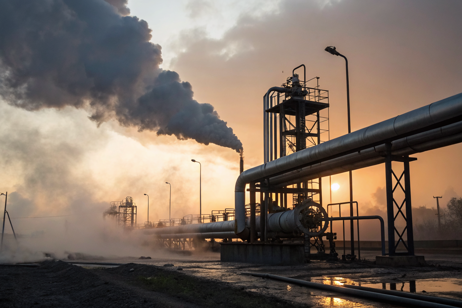
SPCC Piping Requirements: 6 Essential Containment Standards
EPA violations for inadequate piping containment cost facilities an average of $87,000 per incident in 2023. SPCC piping requirements control how oil moves between tanks, preventing environmental disasters that bankrupt companies.
Key Takeaways:
• Double-wall piping systems require annual integrity testing per 40 CFR 112.7
• Buried piping must have cathodic protection systems with 30-day monitoring cycles
• Secondary containment volumes must equal 110% of the largest connected tank capacity
What Are SPCC Piping Requirements?
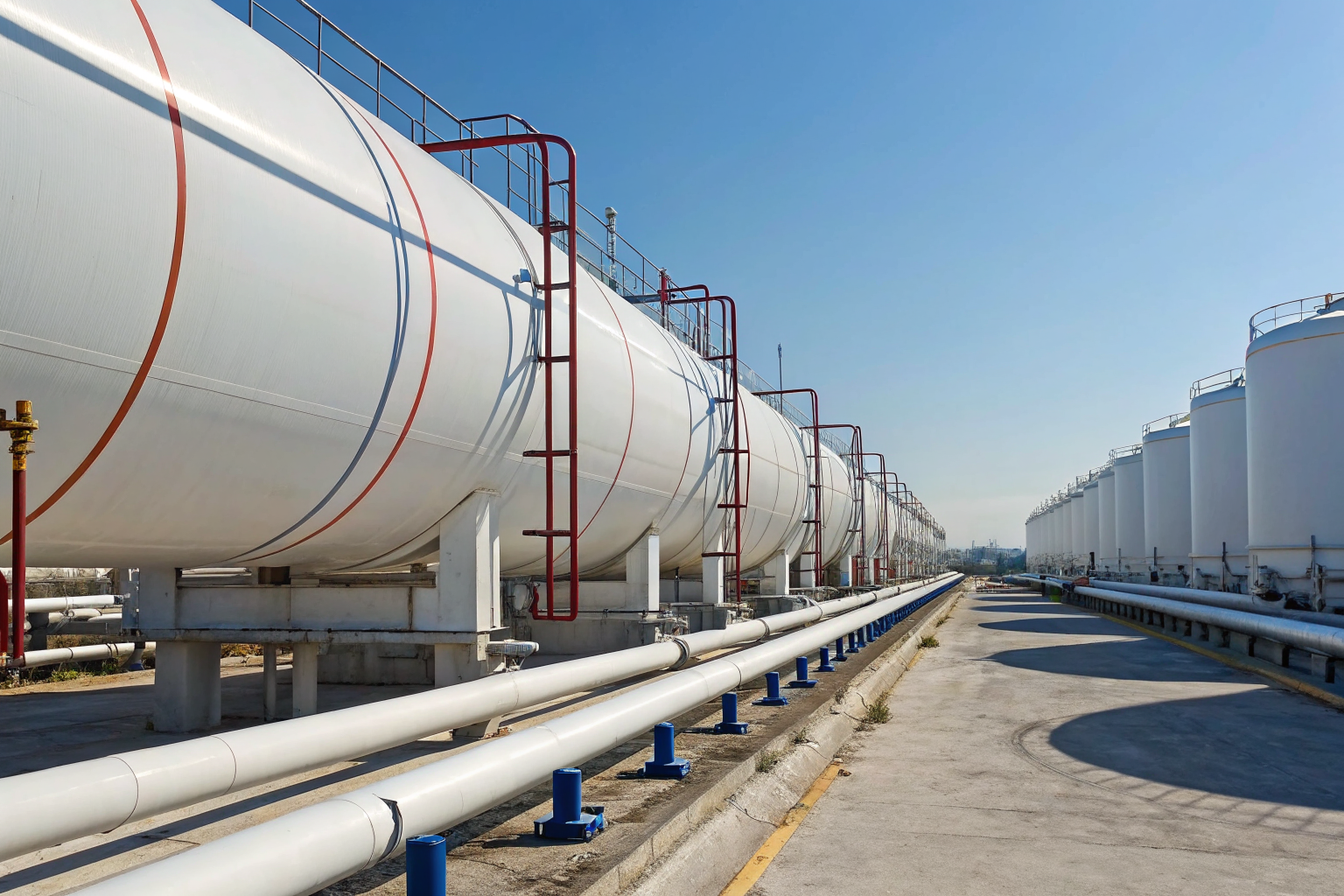
SPCC piping requirements are federal regulations that govern oil transfer systems between storage tanks. These rules appear in 40 CFR 112 under the EPA’s authority to prevent oil spills into navigable waters. SPCC piping requirements regulate every pipe, valve, and fitting that carries oil between containers.
The SPCC Plan must document all piping systems that connect to oil storage tanks. This includes transfer lines, loading arms, and distribution manifolds. EPA Regulations apply to facilities with aggregate oil storage capacity exceeding 1,320 gallons. Facilities with 1,320+ gallon aggregate capacity trigger SPCC requirements.
Piping Systems fall under different standards than tank requirements. Tanks need containment structures like dikes or berms. Pipes need leak detection, pressure monitoring, or double-wall construction. The distinction matters because pipe failures cause different spill patterns than tank ruptures. Pipes release oil along their entire length. Tanks release oil at a single point.
The regulations separate piping into three categories: buried piping, aboveground piping, and piping within secondary containment areas. Each category has specific design standards, testing protocols, and inspection frequencies. Understanding which category applies determines your compliance obligations.
Double-Wall Piping Systems: Design and Testing Standards
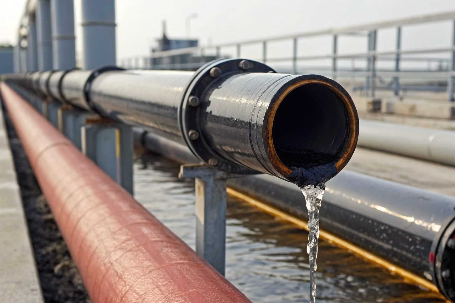
Double-Wall Piping prevents environmental contamination through redundant containment barriers. The inner pipe carries oil while the outer pipe captures any leaks from the primary system. This design eliminates the need for traditional secondary containment structures around piping.
| Component | Specification | Testing Requirement | Maintenance Frequency |
|---|---|---|---|
| Inner Pipe | API 5L or ASTM A53 steel | 150% operating pressure for 4 hours | Annual pressure test |
| Outer Pipe | Corrosion-resistant coating | Vacuum test at -15 inches Hg | Semi-annual vacuum check |
| Annular Space | Continuous monitoring system | 24/7 leak detection | Daily monitoring log |
| End Fittings | Welded or flanged connections | Dye penetrant testing | Quarterly visual inspection |
| Monitoring Wells | Access ports every 1,000 feet | Sensor calibration check | Monthly sensor verification |
Annular space monitoring detects leaks immediately when oil enters the space between pipes. Sensors trigger alarms within 30 seconds of contamination. The monitoring system connects to facility SCADA networks for remote alerting.
Hydrostatic testing verifies pipe integrity before commissioning and annually thereafter. Annual pressure testing at 150% operating pressure for 4-hour duration confirms structural soundness. Test pressure must remain stable within 5% throughout the testing period. Pressure drops indicate leaks requiring immediate repair.
Maintenance schedules prevent catastrophic failures. Daily annular space monitoring catches small leaks before they become major spills. Monthly sensor calibration ensures detection systems function properly. Semi-annual vacuum testing of the outer pipe confirms containment integrity.
How Do You Test Buried Pibing for Compliance?
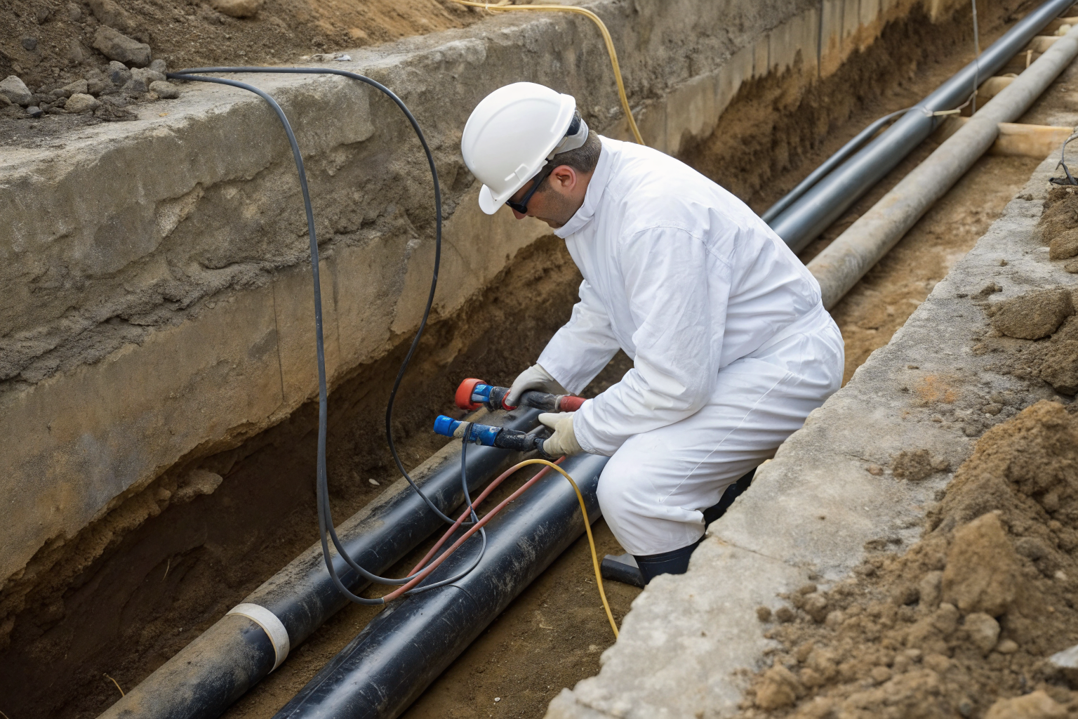
Buried Piping requires cathodic protection systems to prevent corrosion that leads to leaks. The testing process verifies that protective electrical currents maintain pipe integrity below ground. These steps ensure regulatory compliance:
Install cathodic protection rectifiers at 1,000-foot intervals along the pipe run. Rectifiers convert AC power to DC current that flows through soil to the pipe surface. Size rectifiers based on pipe diameter, soil resistivity, and coating condition.
Place reference electrodes at 100-foot spacing to measure soil-to-pipe electrical potential. Copper-copper sulfate electrodes provide stable voltage references for 20+ years. Install electrodes 18 inches deep in native soil, never in backfill material.
Conduct initial potential surveys within 30 days of system startup. Use high-impedance voltmeters to measure pipe-to-soil potentials at each test station. Minimum -850mV potential required for adequate cathodic protection indicates sufficient current flow.
Perform monthly monitoring of all test stations to verify protective levels. Record ambient temperature, soil moisture, and electrical readings in logbooks. Potentials more positive than -850mV require immediate rectifier adjustments.
Execute annual close-interval surveys along the entire pipe length using portable equipment. Take readings every 2.5 feet while walking the pipeline route. This detects coating defects that create high current demand areas.
Inspect coating integrity during scheduled excavations for valve maintenance or repairs. Look for coating disbondment, cracking, or mechanical damage. Document coating condition with photographs and repair defects before backfilling.
Calibrate monitoring equipment quarterly using certified voltage standards. Drift in meter accuracy leads to false readings that mask protection system failures. Replace batteries in portable meters every six months regardless of charge level.
Tank Storage connections require special attention where buried pipes enter tank foundations. Soil settlement creates stress concentrations that damage coating systems. Install flexible couplings and conduct annual excavation inspections at these critical points.
Aboveground Piping Inspection Requirements
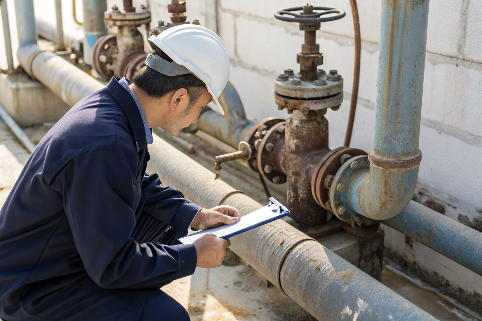
Valve Inspection identifies potential failure points in piping systems before catastrophic releases occur. Visual inspections catch external corrosion, mechanical wear, and gasket deterioration that compromise system integrity. These inspections prevent the majority of piping-related spills.
Monthly visual inspections examine all accessible piping components for signs of deterioration. Look for rust stains, wet spots, or discolored soil that indicate leaks. Check pipe supports for damage that creates stress points. Inspect insulation systems for gaps that expose pipe to weather. Document findings with photographs and GPS coordinates for tracking.
Piping Systems require different inspection techniques based on their location and function. Transfer lines need pressure gauge monitoring during operations. Loading arms need swing joint lubrication and seal replacement. Manifold systems need block valve cycling to prevent seizure.
Quarterly operational valve testing cycles verify that isolation valves function properly during emergencies. Test each valve under normal operating pressure by closing and reopening while monitoring downstream pressure. Valves that don’t achieve full shutoff within 30 seconds need immediate maintenance. Replace valve seats and seals that show wear patterns.
Joint integrity checks focus on flanged connections where most leaks develop. Torque bolts to manufacturer specifications using calibrated wrenches. Look for gasket extrusion or bolt corrosion that indicates over-tightening or chemical attack. Replace spiral wound gaskets every five years regardless of apparent condition.
Environmental Compliance requires documentation of all inspection activities. Maintain inspection logs with dates, findings, and corrective actions taken. Include photographs of problem areas and repair work. Train inspectors to recognize early warning signs that prevent major releases.
Secondary Containment Volume Calculations
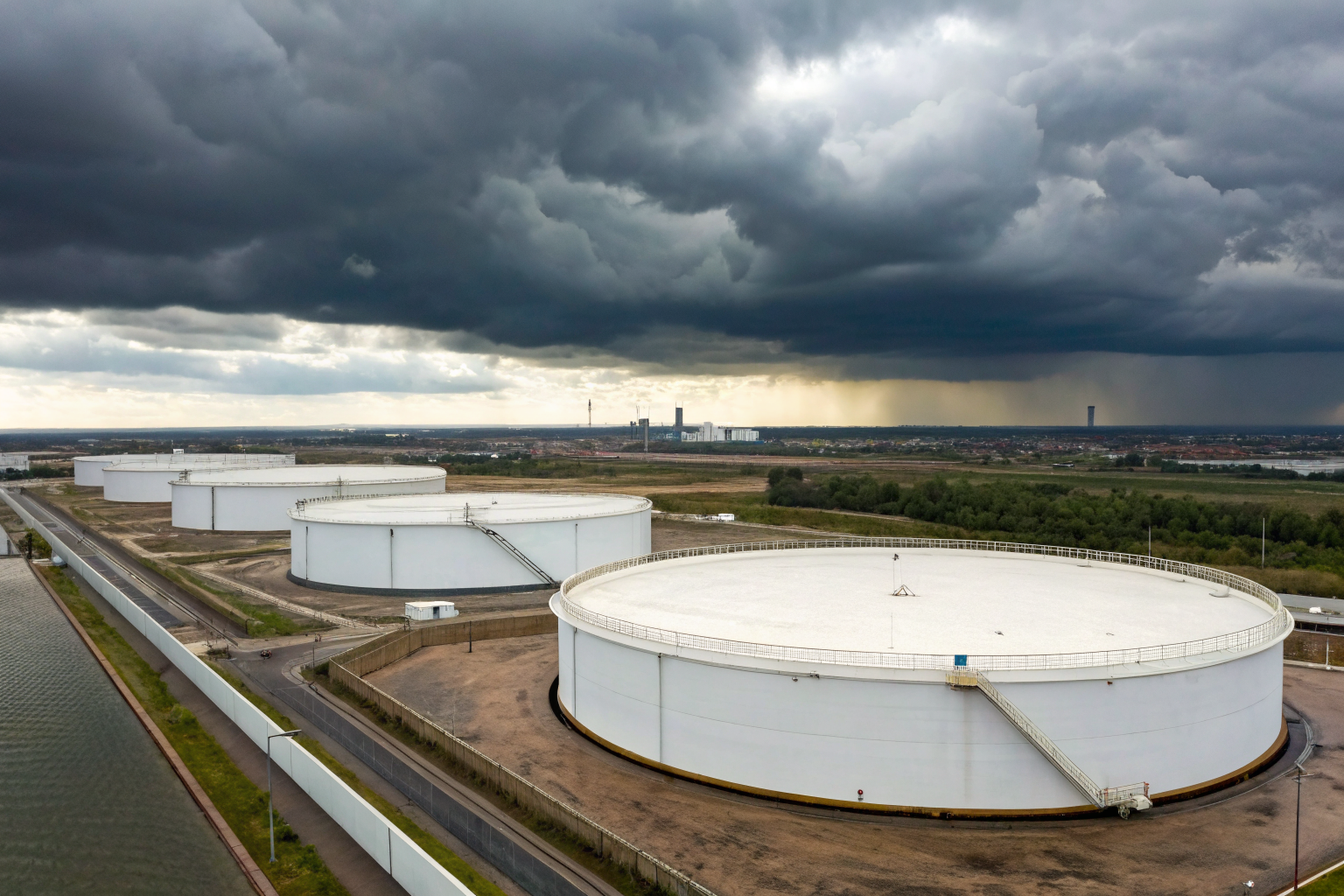
Secondary Containment must equal 110% largest tank capacity connected to the piping system. This sizing ensures adequate volume to capture the worst-case spill scenario. The calculation includes precipitation allowances and freeboard requirements that many facilities miss.
| Tank Size (gallons) | Required Containment (gallons) | 24-Hour Precipitation (gallons) | Total Volume Needed (gallons) |
|---|---|---|---|
| 10,000 | 11,000 | 2,640 | 15,004 |
| 25,000 | 27,500 | 2,640 | 33,154 |
| 50,000 | 55,000 | 2,640 | 63,404 |
| 100,000 | 110,000 | 2,640 | 123,904 |
| 250,000 | 275,000 | 2,640 | 303,904 |
Freeboard calculations add 10% to the base containment volume for wave action and thermal expansion. A 100,000-gallon tank needs 110,000 gallons base containment plus 11,000 gallons freeboard equals 121,000 gallons minimum.
24-hour precipitation event plus 10% freeboard in containment sizing accounts for rainfall during spill response operations. Use local weather data to determine the 25-year storm event precipitation volume. Most regions require 2,640 gallons per acre of containment surface area.
Drainage considerations affect net containment capacity. Containment areas with gravity drains lose volume to pipe invert elevations. Pump systems maintain full containment volume but need backup power during emergencies. Calculate actual containment volume using surveyed elevations, not design drawings.
Multiple tank scenarios require containment sized for the largest single tank, not aggregate capacity. Three 50,000-gallon tanks need 55,000-gallon containment, not 165,000 gallons. The assumption is that only one tank fails at a time during normal operations.
What Documentation Must You Maintain?

SPCC Plan requires updated piping documentation whenever system modifications occur. The plan must include current piping diagrams, inspection schedules, and testing procedures for all oil transfer systems. Documentation proves regulatory compliance during EPA inspections.
Inspection logs document the frequency and findings of all piping system evaluations. Record visual inspection results, valve testing outcomes, and cathodic protection measurements in bound logbooks. Include inspector signatures and dates for legal authenticity. Maintain separate logs for each piping system to simplify record retrieval.
Testing certificates verify that pressure testing, leak detection calibration, and cathodic protection surveys meet regulatory standards. Include test pressures, duration, acceptance criteria, and technician certifications. Keep certificates from third-party testing companies that provide independent verification of system integrity.
Amendment triggers require SPCC Plan updates within six months of piping modifications. New pipe installations, valve replacements, or routing changes constitute significant modifications. Submit amended plans to EPA within 60 days if the facility meets Tier I reporting requirements.
Environmental Compliance depends on complete documentation that demonstrates regulatory adherence. Missing records during inspections result in violations regardless of actual system condition. 3-year retention minimum for all inspection and testing records provides adequate coverage for enforcement periods. Store records in fireproof cabinets or digital systems with backup copies at separate locations.
EPA Regulations require immediate notification for any discharge that reaches navigable waters or threatens public health. Maintain emergency contact lists with 24-hour notification procedures. Include local response contractors, regulatory agencies, and corporate environmental staff in notification matrices.