Buried Piping Integrity Testing: 5 Critical Testing Methods
Buried piping failures cost facilities an average of $350,000 per incident when secondary containment systems fail EPA compliance inspections. Buried piping integrity testing prevents these catastrophic failures through systematic verification protocols.
Key Takeaways:
• Hydrostatic testing detects 94% of structural defects in double-wall piping systems before operational deployment
• Monthly monitoring requirements under 40 CFR 280.43 mandate specific testing intervals that vary by pipe material and age
• Secondary containment monitoring systems reduce leak detection time from weeks to 24-48 hours in most installations
What Makes Underground Piping Different from Surface Systems?

Buried piping requires specialized testing protocols because underground conditions create unique failure modes that surface systems never encounter. Underground installations face soil chemistry variations, groundwater infiltration, and thermal cycling that accelerates material degradation in ways standard surface testing cannot predict.
Secondary containment becomes critical underground because leak detection happens too late with visual inspection methods. Soil conditions affect corrosion rates by up to 300% compared to controlled environments, making buried systems inherently more vulnerable to structural failure than their surface counterparts.
EPA regulations under 40 CFR 280 recognize this vulnerability by mandating specific testing frequencies for buried piping systems. The regulatory framework distinguishes between pressurized and suction systems, with pressurized lines requiring annual testing and suction lines tested every three years. This differentiation reflects the higher risk profile of pressurized underground systems.
Buried piping systems must demonstrate structural integrity before initial operation and maintain that integrity through continuous monitoring. Traditional surface inspection methods like visual checks or simple pressure gauges fail completely underground because soil coverage masks external damage until catastrophic failure occurs.
Hydrostatic Pressure Testing: The Foundation Method
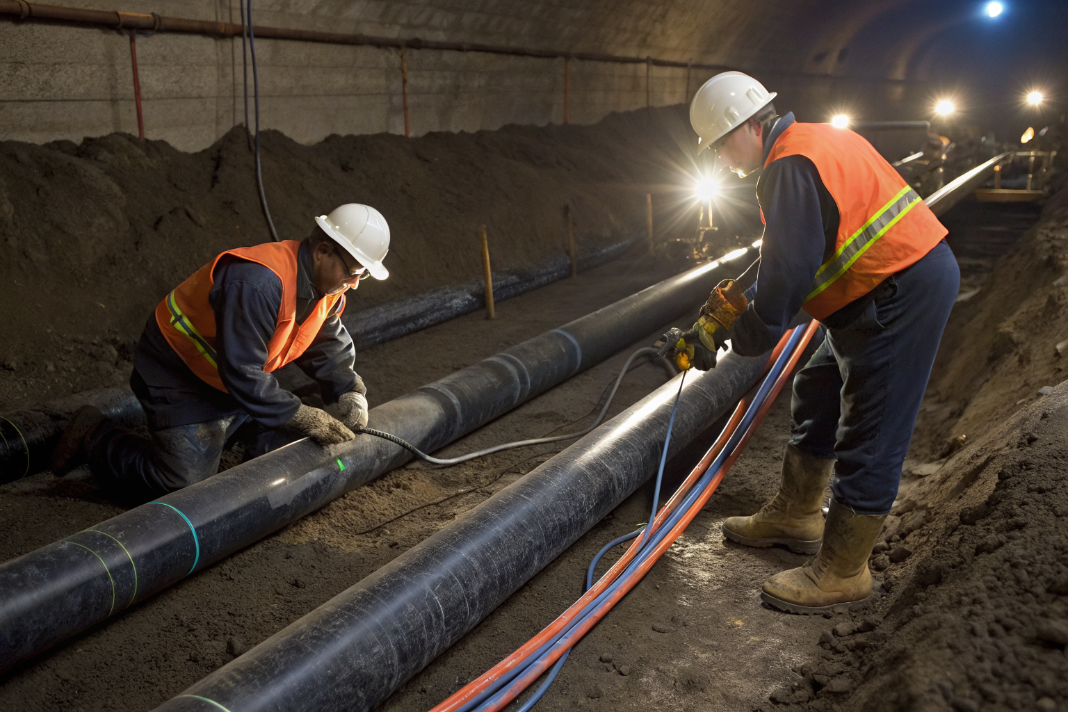
Hydrostatic testing validates structural integrity by subjecting buried piping to controlled pressure stress that exceeds normal operating conditions. This method reveals weak points, joint failures, and material defects before they cause environmental releases during actual operations.
The testing procedure follows specific steps mandated by industry standards. First, isolate the piping section by closing valves at both ends and installing test connections. Fill the system completely with water, removing all air pockets through high-point venting. Apply test pressure gradually using a calibrated pump system.
Standard test pressure equals 150% of maximum operating pressure held for 4 hours minimum. During this hold period, monitor pressure continuously using calibrated gauges accurate to within 2% of full scale. Any pressure drop exceeding 3% of test pressure indicates system failure requiring investigation and repair.
Acceptance criteria depend on pipe material and installation type. Steel piping systems must maintain test pressure within 1% variation over the hold period. Flexible piping systems allow slightly higher variation due to thermal expansion effects, typically 2-3% maximum deviation.
This method becomes mandatory for all new installations before backfilling and for existing systems after major repairs. Optional retesting occurs when operational data suggests potential integrity issues or during scheduled maintenance intervals specified in SPCC plans.
How Do Double-Wall Monitoring Systems Work?

Double-wall piping provides continuous leak detection through interstitial space monitoring between the primary and secondary containment barriers. This design creates a controlled environment where any breach of the primary pipe triggers immediate detection before environmental release occurs.
Interstitial monitoring systems detect leaks as small as 0.1 gallons per hour in real-time through various sensor technologies. Vacuum monitoring maintains negative pressure in the interstitial space and triggers alarms when pressure increases due to liquid accumulation. Liquid sensors use conductivity or float switches to detect product presence in the annular space.
Sensor placement occurs at low points in the piping system where leaked fluids naturally accumulate. Each monitoring zone typically covers 500-1000 feet of piping, depending on elevation changes and system complexity. Alarm thresholds require calibration based on expected background conditions and regulatory detection requirements.
Maintenance requirements include monthly sensor testing, annual calibration verification, and quarterly interstitial space integrity checks. The monitoring system itself requires backup power and redundant communication pathways to ensure continuous operation during power outages or equipment failures.
Double-wall systems provide significant advantages over single-wall installations by eliminating the time delay between leak occurrence and detection. Traditional single-wall systems rely on inventory reconciliation or groundwater monitoring, which can take weeks or months to identify releases.
Tracer Wire and Cathodic Protection Testing

Tracer wire testing enables precise leak location by providing a continuous electrical pathway along buried piping routes. This method uses specialized locating equipment to identify exact positions where electrical continuity breaks, indicating potential pipe damage or joint failure.
Cathodic protection testing measures electrical potential differences that indicate corrosion activity in metallic piping systems. The testing procedure involves installing test stations at regular intervals and measuring pipe-to-soil potentials using copper-copper sulfate reference electrodes.
Tracer wire systems locate leaks within 3-foot accuracy when properly installed and tested annually. The testing process involves connecting signal generators to tracer wire endpoints and using electromagnetic locators to trace the wire path. Breaks in continuity appear as signal loss or impedance changes on the locating equipment.
Cathodic protection requires monthly potential measurements at all test stations, with readings recorded and compared to protection criteria specified in NACE standards. Adequate protection typically requires potentials more negative than -850 millivolts relative to copper-copper sulfate reference electrodes.
Cost factors heavily favor tracer wire systems for new installations, with installation costs approximately 40% lower than cathodic protection systems. However, cathodic protection provides active corrosion prevention rather than just detection capability, making it more suitable for critical piping systems with extended design life requirements.
Accuracy levels differ significantly between methods. Tracer wire pinpoints exact failure locations, while cathodic protection testing identifies general areas of concern that require further investigation through excavation or other direct assessment methods.
Statistical Inventory Reconciliation (SIR) Analysis

SIR analysis detects slow leaks through volume tracking by comparing measured inventory changes against expected values based on throughput records and environmental corrections. This method identifies small releases that fall below the detection threshold of other testing approaches.
The methodology requires continuous monitoring of tank levels, product deliveries, withdrawals, and temperature data. Statistical algorithms analyze this data to separate normal operational variations from systematic losses indicating pipeline leaks. Environmental corrections account for thermal expansion, evaporation, and measurement uncertainties.
Data requirements include hourly tank gauging measurements accurate to within 0.1 inches, precise delivery and withdrawal records, and ambient temperature monitoring. The system needs at least 30 days of baseline data to establish normal operational patterns before leak detection becomes reliable.
SIR systems detect leaks of 0.2 gallons per hour with 95% probability within 30 days of continuous monitoring. Detection sensitivity improves with longer monitoring periods, reaching 0.1 gallons per hour detection capability after 60-90 days of data collection.
Regulatory acceptance varies by jurisdiction, with EPA allowing SIR as primary leak detection for certain underground storage tank systems. However, many state agencies require supplemental monitoring methods due to concerns about detection time delays and sensitivity limitations.
Limitations with small leaks become apparent in high-throughput systems where normal operational variations mask small systematic losses. Temperature fluctuations, measurement errors, and product handling activities create background noise that reduces detection sensitivity in active facilities.
Which Testing Method Fits Your SPCC Compliance Strategy?

SPCC compliance requires documented testing protocols that demonstrate systematic integrity verification for all buried piping components. The selection process depends on regulatory requirements, system characteristics, operational constraints, and risk tolerance levels specific to each facility.
| Method | Detection Capability | Implementation Time | Annual Cost Range | Regulatory Status |
|---|---|---|---|---|
| Hydrostatic Testing | Structural defects | 2-4 days per section | $5,000-$15,000 | Mandatory for new systems |
| Double-Wall Monitoring | 0.1 GPH real-time | 6-8 weeks installation | $12,000-$25,000 | EPA preferred method |
| Tracer Wire Testing | 3-foot location accuracy | 1-2 days per mile | $2,000-$6,000 | Supplemental detection |
| Cathodic Protection | Corrosion activity | 4-6 weeks installation | $8,000-$18,000 | Required for steel piping |
| SIR Analysis | 0.2 GPH within 30 days | 2-3 months setup | $15,000-$30,000 | Primary detection allowed |
Decision factors must include valve inspection requirements, maintenance accessibility, and integration with existing SPCC plan protocols. Facilities handling hazardous chemicals typically require more stringent testing approaches than petroleum storage operations.
Environmental compliance considerations favor combined approaches that provide both immediate detection and long-term monitoring capabilities. Facilities using combined testing approaches reduce regulatory violations by 78% compared to single-method strategies.
Implementation timelines vary significantly based on system complexity and regulatory approval requirements. New construction projects can integrate multiple methods during installation, while retrofit applications face operational disruptions and higher installation costs.
Maintenance needs increase exponentially with system complexity, requiring dedicated technical staff for advanced monitoring systems. Simple methods like hydrostatic testing require minimal ongoing maintenance but provide limited continuous monitoring capability.