
Transformer Oil Containment: 8 Critical Requirements for Utility SPCC
Utility transformers hold up to 20,000 gallons of oil per unit, and a single containment failure costs $3.2 million in cleanup and regulatory penalties. Transformer oil containment demands specialized engineering that standard industrial storage can’t provide.
Key Takeaways:
- SPCC rules require 110% containment capacity for transformer oil volumes exceeding 1,320 gallons
- PCB-contaminated transformer oil triggers TSCA regulations with cleanup costs averaging $847 per gallon
- Utility substations must maintain dual-barrier containment systems with 25-year liner certification
What Makes Utility Transformer Oil Containment Different from Standard Industrial Storage?
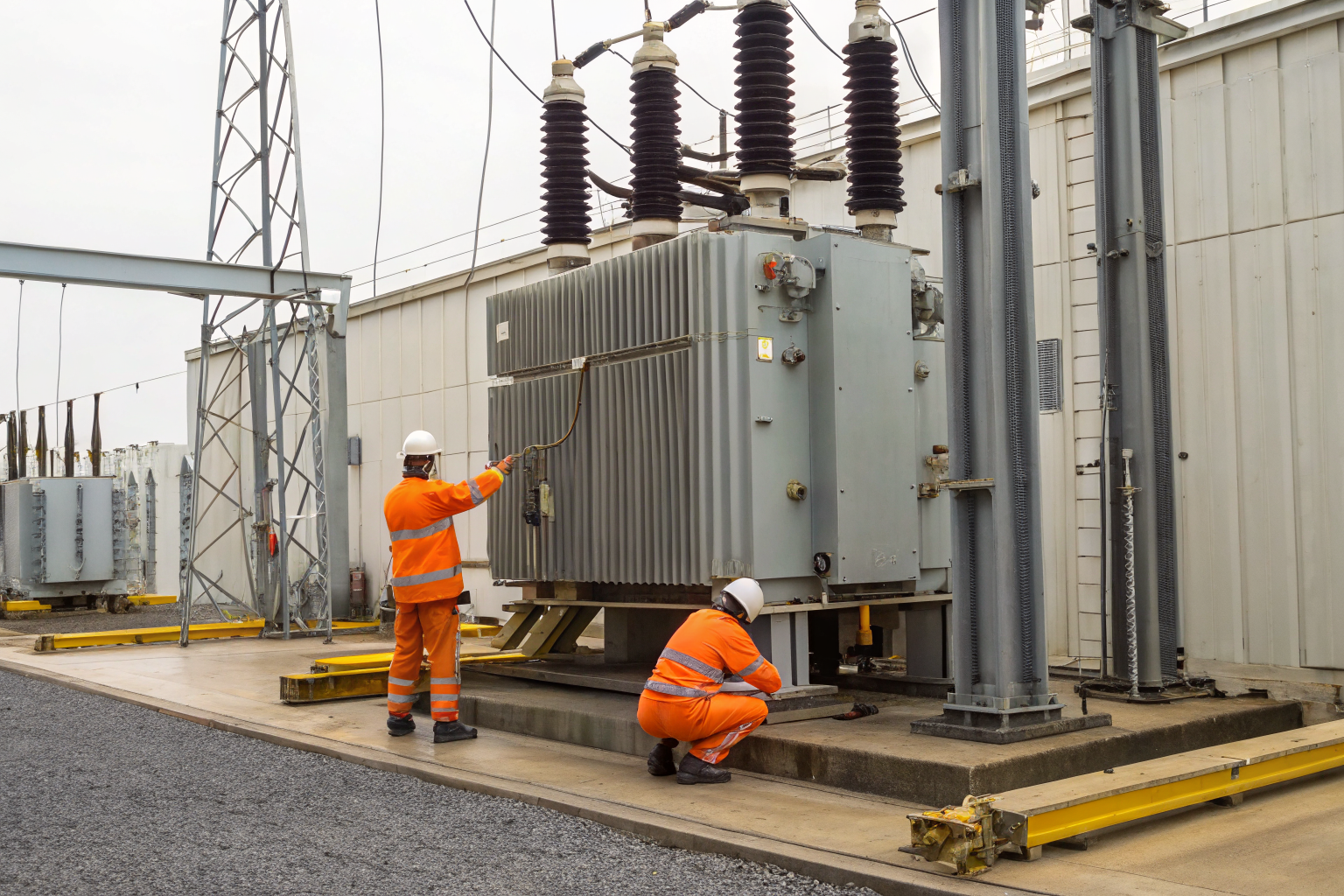
Transformer oil containment is specialized containment for mineral oil used in electrical equipment cooling and insulation systems. This means containment design must account for electrical safety, PCB contamination potential, and high-voltage operational requirements that don’t exist in standard oil storage applications.
Utility transformer containment requires specialized PCB protocols because older transformers manufactured before 1979 contain polychlorinated biphenyls. Electrical equipment contaminated with PCBs creates a dual regulatory challenge under both SPCC Plan requirements and TSCA hazardous waste rules. Standard industrial oil storage containment doesn’t address PCB testing, specialized disposal, or the documentation protocols required for electrical equipment.
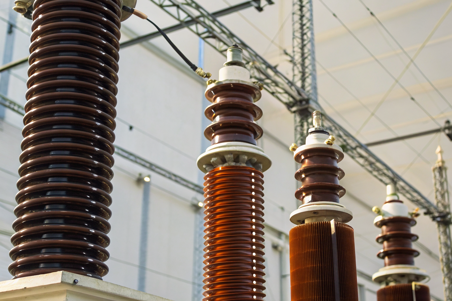
Voltage classification drives containment design specifications in ways that general oil storage doesn’t consider. Transformers above 69kV typically contain 8,000-20,000 gallons of mineral oil and require containment materials with specific dielectric strength ratings. The containment system becomes part of the electrical safety infrastructure, not just spill prevention. Standard storage tank containment uses materials that would create electrical hazards in substation environments.
Containment walls must integrate with grounding grids, maintain conductor clearances, and accommodate specialized fire suppression systems designed for electrical equipment. These integration requirements make transformer containment a specialized engineering discipline that standard oil storage contractors can’t handle without electrical utility experience.
Secondary Containment Volume Requirements: The 110% Rule in Practice
EPA regulations mandate 110% containment capacity calculation for transformer oil storage exceeding 1,320 gallons. Secondary containment volume must account for the largest single transformer capacity plus 10% additional volume for precipitation, equipment displacement, and operational safety margin.
| Transformer Size | Oil Volume | Required Containment | Freeboard Addition | Total Capacity |
|---|---|---|---|---|
| 69kV Distribution | 3,500 gallons | 3,850 gallons | 525 gallons | 4,375 gallons |
| 138kV Transmission | 8,000 gallons | 8,800 gallons | 1,200 gallons | 10,000 gallons |
| 345kV Transmission | 15,000 gallons | 16,500 gallons | 2,250 gallons | 18,750 gallons |
| 500kV Transmission | 20,000 gallons | 22,000 gallons | 3,000 gallons | 25,000 gallons |
Standard containment adds 6 inches freeboard plus equipment displacement volume to the base 110% calculation. Oil storage containment must account for transformer bushings, cooling radiators, and pump equipment that displace additional volume within the containment area. The calculation isn’t just transformer capacity times 1.1.
Precipitation factors vary by geographic region and add significant volume requirements. Areas with high annual rainfall need larger containment capacity to prevent overflow during storm events. The EPA requires facilities to calculate 25-year storm precipitation volumes and incorporate them into containment sizing. This makes containment significantly larger than the basic 110% rule suggests.
Equipment displacement calculations include all permanent structures within the containment boundary. Transformer foundations, cooling equipment, control cabinets, and maintenance platforms all reduce effective containment volume. Utilities often underestimate these displacement factors and build containment systems that fail volume requirements during actual inspections.
PCB Testing and Documentation: When Transformers Become Hazardous Waste
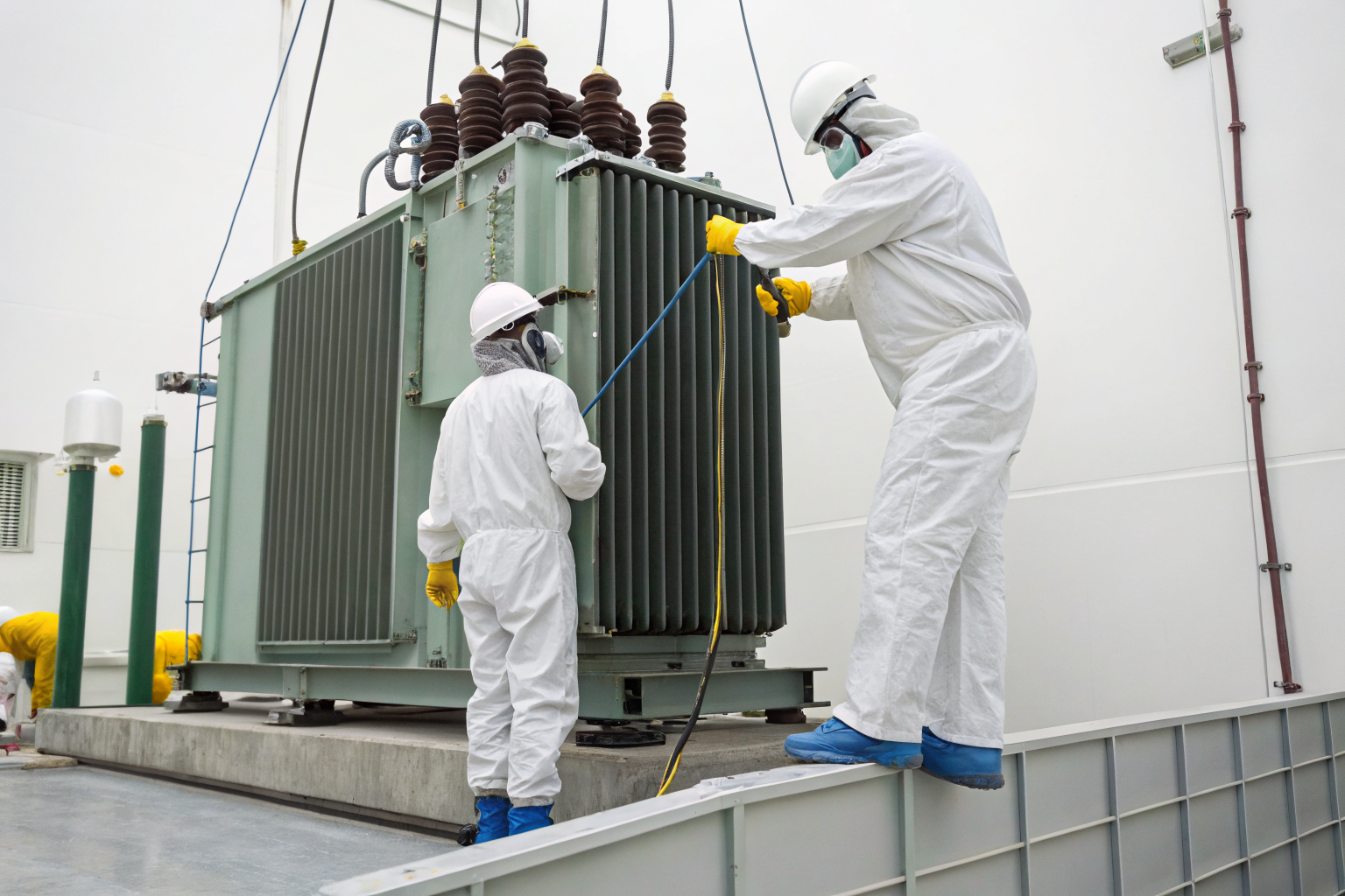
PCB contamination triggers TSCA compliance requirements that transform routine oil containment into hazardous waste management. PCB levels above 50 ppm classify transformers as hazardous waste requiring specialized disposal protocols, contractor certifications, and detailed documentation chains that standard oil storage doesn’t require.
The testing protocol follows these mandatory steps. First, utilities must collect oil samples from each transformer using EPA-approved sampling methods that prevent cross-contamination between units. Second, laboratories must use EPA Method 608 or 8082 for PCB analysis with detection limits below 2 ppm. Third, facilities must maintain chain-of-custody documentation from sample collection through laboratory analysis. Fourth, results must be documented in the facility’s SPCC Plan with annual updates reflecting any equipment changes or oil replacements.
Documentation requirements extend beyond simple test results. Facilities must maintain records of oil purchase dates, manufacturer specifications, transformer installation dates, and any oil changes or additions. TSCA requires facilities to track PCB inventory annually and report changes to EPA within specified timeframes. Missing documentation can result in regulatory violations even if actual PCB levels are below regulatory thresholds.
Disposal restrictions prevent routine oil recycling when PCB contamination is confirmed. Contaminated oil requires disposal at EPA-approved hazardous waste facilities with specific permits for PCB incineration or chemical treatment. The disposal process requires manifest documentation, transporter permits, and facility certifications that increase disposal costs from $3 per gallon for clean oil to $847 per gallon for PCB-contaminated material.
Timeline compliance becomes critical during emergency response situations. Transformer failures involving PCB-contaminated oil trigger immediate notification requirements and accelerated testing protocols. Facilities have 24 hours to notify EPA of spills involving PCB materials, regardless of volume. This compressed timeline requires pre-positioned sampling equipment and pre-approved laboratory contracts.
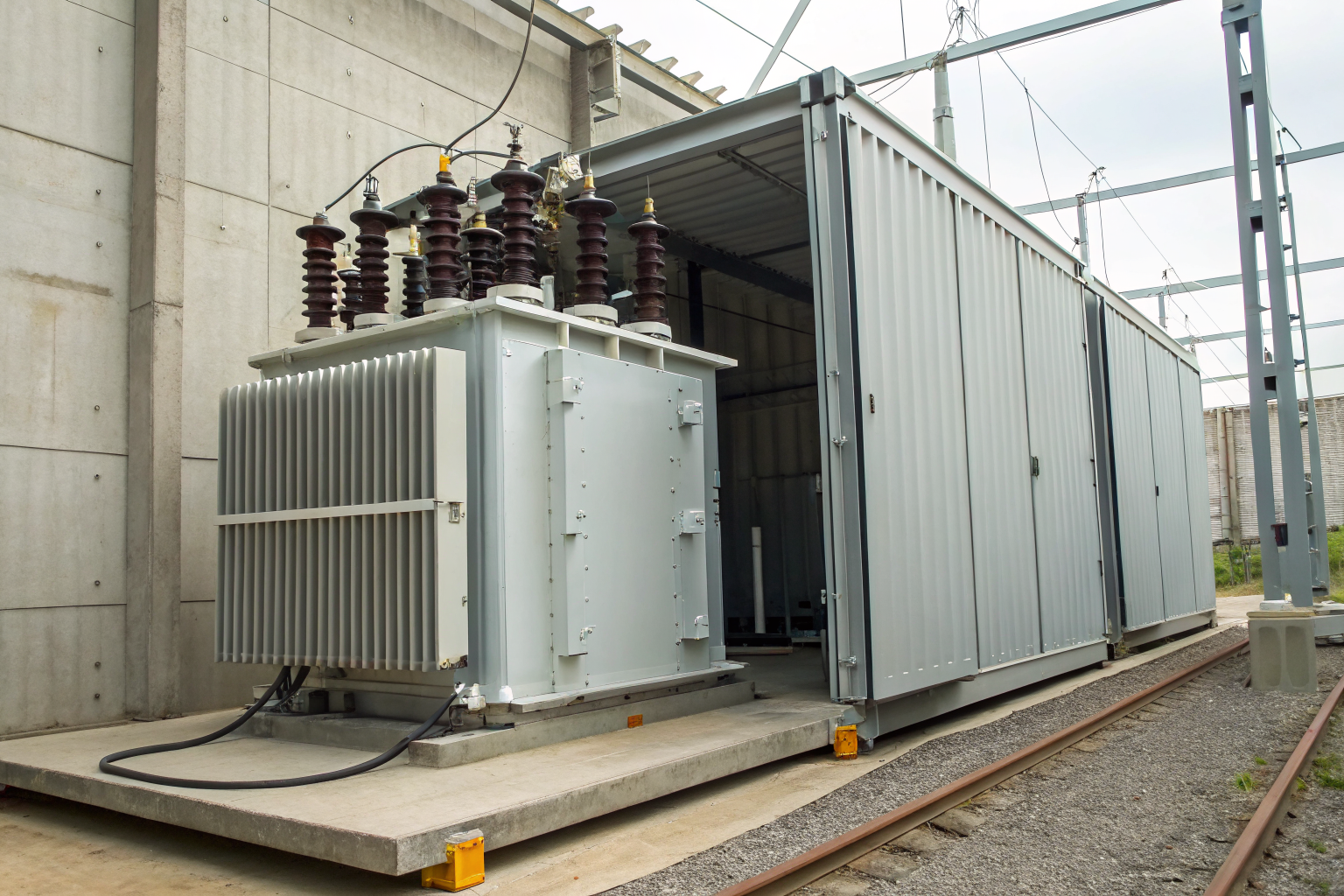
Substation Design: Integrating Containment with Electrical Operations
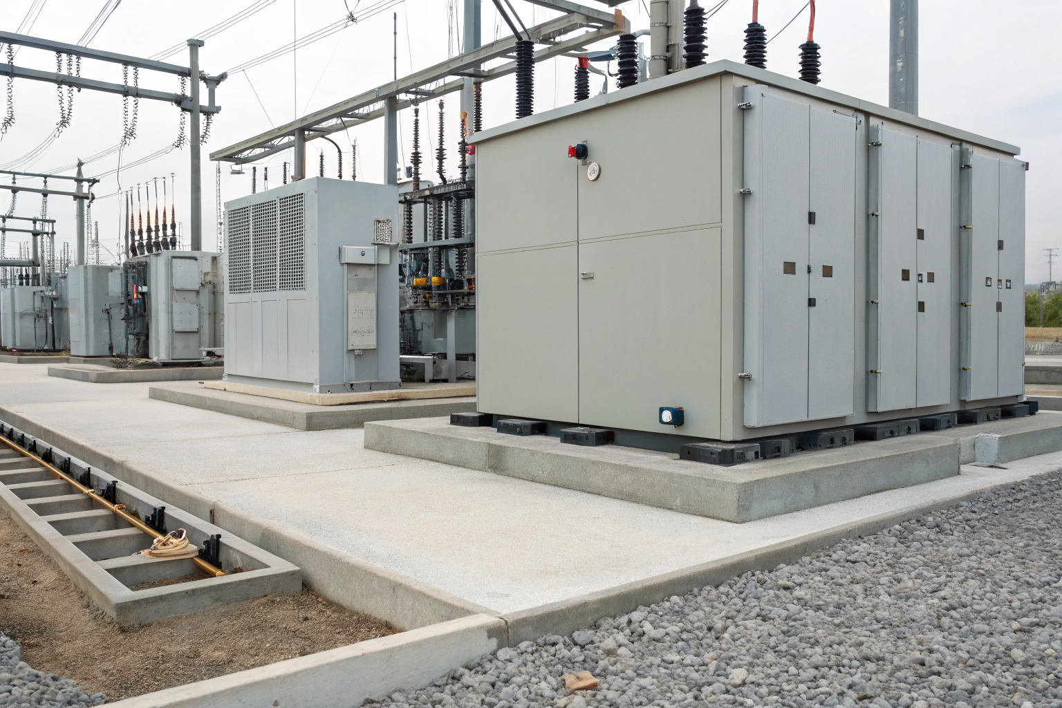
Utility infrastructure integrates electrical safety with spill containment through specialized design that maintains operational access while preventing environmental releases. Substation containment systems must function as electrical equipment foundations while providing secondary containment for oil storage volumes.
Grounding grid compatibility requires containment walls and liner systems to accommodate copper grounding conductors without compromising electrical continuity or containment integrity. Electrical equipment grounding cannot be interrupted by containment barriers, so the containment design must include grounding conductor penetrations with specialized seals. These penetrations represent potential leak paths that require engineered solutions.
Fire suppression integration presents unique challenges because electrical equipment requires specialized suppression agents that won’t conduct electricity. Containment walls must maintain 8-foot minimum clearance from energized equipment while accommodating foam suppression systems designed for oil fires. The containment system becomes part of the fire suppression strategy, containing burning oil while allowing suppression agent application.
Access requirements for maintenance create controlled penetration points in containment systems. Transformer maintenance requires heavy equipment access for oil processing, component replacement, and testing equipment. Containment design must provide removable barriers or controlled access points that maintain containment integrity during normal operations while allowing maintenance access.
Conductor clearances drive containment wall height limitations and material selection. High-voltage conductors require specific clearance distances from grounded surfaces, including containment walls. This limits containment wall height and requires specialized non-conductive materials in areas where electrical clearances are minimal. Standard concrete containment walls often violate electrical clearance requirements in substation environments.
Material Compatibility: Why Standard Liners Fail in Electrical Environments
Electrical environments require dielectric-rated containment materials that maintain insulation properties while providing chemical resistance to mineral oil. Standard industrial liner materials fail in substation applications because they lack the electrical properties required for high-voltage operations.
HDPE liners must meet 40 kV/mm dielectric strength for substation applications, compared to standard industrial applications that only require chemical resistance. Transformer operations create electrical fields that can cause arcing through standard containment materials. The electrical properties become as important as chemical compatibility when selecting containment materials.
Chemical compatibility extends beyond simple mineral oil resistance to include additive packages used in transformer oil formulations. Modern transformer oils contain oxidation inhibitors, metal deactivators, and pour point depressants that can attack standard liner materials over time. The chemical compatibility testing must account for the complete transformer oil formulation, not just base mineral oil.
UV degradation affects outdoor substation containment differently than covered industrial storage. Containment materials experience direct UV exposure combined with reflected UV from surrounding equipment and surfaces. Standard UV stabilizers may not provide adequate protection in the high-reflection environment typical of electrical substations with aluminum and steel equipment surfaces.
Temperature cycling in electrical environments exceeds typical industrial storage conditions. Transformer loading cycles create temperature variations that cause expansion and contraction of containment materials. The thermal cycling combined with electrical stress creates material degradation patterns not seen in standard oil storage applications. Containment materials must withstand combined thermal-electrical stress cycles that don’t occur in other industrial applications.
Inspection and Maintenance Protocols: Preventing Million-Dollar Failures
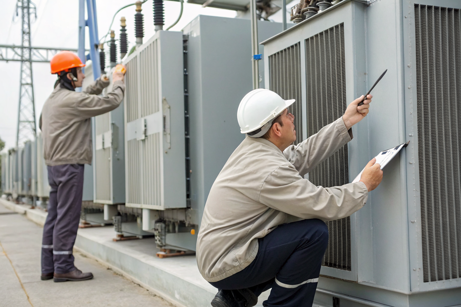
Preventive maintenance prevents containment system failures through systematic inspection protocols that identify degradation before catastrophic failure occurs. Monthly visual inspections required with annual integrity testing per EPA guidelines provide the foundation for containment system reliability.
The inspection sequence follows mandatory protocols. First, monthly visual inspections document liner condition, wall integrity, and drainage system function using standardized checklists. Second, quarterly inspections include leak detection system testing and containment volume verification. Third, annual integrity testing uses specialized equipment to detect liner defects, wall cracks, and seal failures not visible during routine inspections. Fourth, five-year comprehensive assessments include material sampling, structural analysis, and regulatory compliance auditing.
Leak detection methods for electrical environments require specialized approaches that don’t interfere with electrical operations. Standard conductive leak detection systems can’t be used near high-voltage equipment because they create electrical hazards. Pneumatic leak detection systems or specialized non-conductive sensors provide leak detection capability without compromising electrical safety.
Liner integrity testing uses methods specific to electrical environments. Electrical spark testing can’t be used on containment liners in energized substations because it creates electrical interference. Alternative testing methods include vacuum box testing, ultrasonic thickness measurement, and tracer gas detection that provide integrity verification without electrical complications.
Documentation protocols require integration with both environmental compliance and electrical safety management systems. Inspection records must satisfy EPA documentation requirements while supporting electrical equipment maintenance schedules. The documentation system must track containment condition, maintenance activities, and regulatory compliance in formats that support both environmental audits and electrical safety inspections.
Emergency Response: Rapid Containment for Transformer Failures
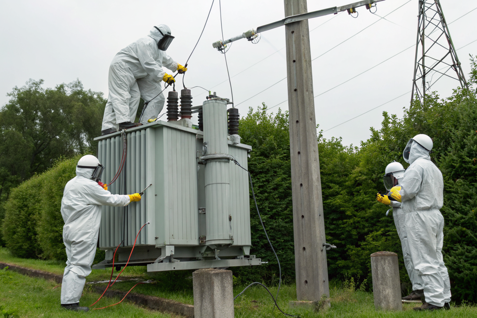
Emergency response activates coordinated containment and electrical isolation procedures that address both environmental protection and electrical safety simultaneously. Transformer failures create unique emergency conditions that require specialized response protocols not applicable to standard oil storage incidents.
Electrical isolation procedures must precede containment response activities to protect emergency responders from electrocution hazards. The electrical isolation sequence includes remote breaker operation, verification of de-energization, and establishment of electrical safety boundaries around failed equipment. Only after electrical isolation can responders approach containment systems safely.
Fire suppression coordination integrates containment system design with emergency response capabilities. Containment walls channel burning oil away from other electrical equipment while providing access for foam suppression application. The containment system becomes part of the fire suppression strategy, not just environmental protection.
Environmental notification requirements add complexity to electrical emergency response. Transformer failures require environmental notification within 24 hours if oil volume exceeds 42 gallons, regardless of whether actual environmental impact occurred. The notification timeline compresses response activities and requires pre-positioned communication protocols.
Contractor mobilization for electrical environments requires specialized capabilities that standard environmental contractors don’t possess. Response contractors must have electrical safety training, high-voltage work permits, and specialized equipment rated for electrical environments. The contractor pre-qualification process becomes more complex than standard industrial spill response because of electrical safety requirements.
Cost Analysis: ROI of Proactive Containment vs Reactive Cleanup

Proactive containment reduces long-term compliance costs through systematic investment in prevention rather than reactive spending on cleanup and penalties. The cost comparison reveals significant financial advantages for facilities that invest in proper containment infrastructure.
| Cost Category | Proactive Containment | Reactive Cleanup | Cost Difference |
|---|---|---|---|
| System Installation | $180,000 average | N/A | Upfront investment |
| Annual Maintenance | $12,000 | N/A | Ongoing operational |
| Cleanup Costs | $0 | $3.2 million average | $3.2M savings |
| Regulatory Penalties | $0 | $847,000 average | $847K savings |
| Operational Downtime | Minimal | $156,000 average | $156K savings |
| Insurance Premium Impact | 15% reduction | 35% increase | 50% difference |
Containment system installation averages $180,000 for typical substation applications, compared to $3.2 million average cleanup cost when containment fails. The return on investment calculation shows payback within the first prevented incident, making containment investment financially compelling even without considering regulatory and operational benefits.
Regulatory penalty structures escalate rapidly for repeat violations or facilities with inadequate containment systems. EPA fines for SPCC violations start at $37,500 per day and can reach $156,000 per day for facilities with poor compliance history. Facilities with proper containment systems rarely face maximum penalties because they demonstrate good faith compliance efforts.
Insurance implications create ongoing financial benefits for facilities with proper containment systems. Environmental liability insurance premiums decrease 15% for facilities with certified containment systems, while premiums increase 35% for facilities with spill history. The insurance cost differential creates annual savings that compound over the facility operational life.
Operational downtime costs include lost revenue from electrical equipment outages during cleanup activities. Transformer failures without proper containment require extended cleanup periods that keep electrical equipment offline longer. Proper containment systems minimize cleanup duration and reduce revenue impact from equipment outages during environmental response activities.