Secondary Containment Drainage Requirements: Managing Stormwater and Drain Valves
Secondary containment systems that can’t properly manage water become compliance nightmares and environmental liabilities within months of installation. Understanding secondary containment drainage requirements prevents costly violations and protects your facility from regulatory scrutiny.
Key Takeaways:
• EPA requires drain valves to remain closed during normal operations per 40 CFR 112.8
• Precipitation removal must occur within 24-48 hours to prevent overflow violations
• Manual inspection protocols reduce containment failure rates by 67% compared to automated-only systems
What Are Secondary Containment Drainage Requirements?
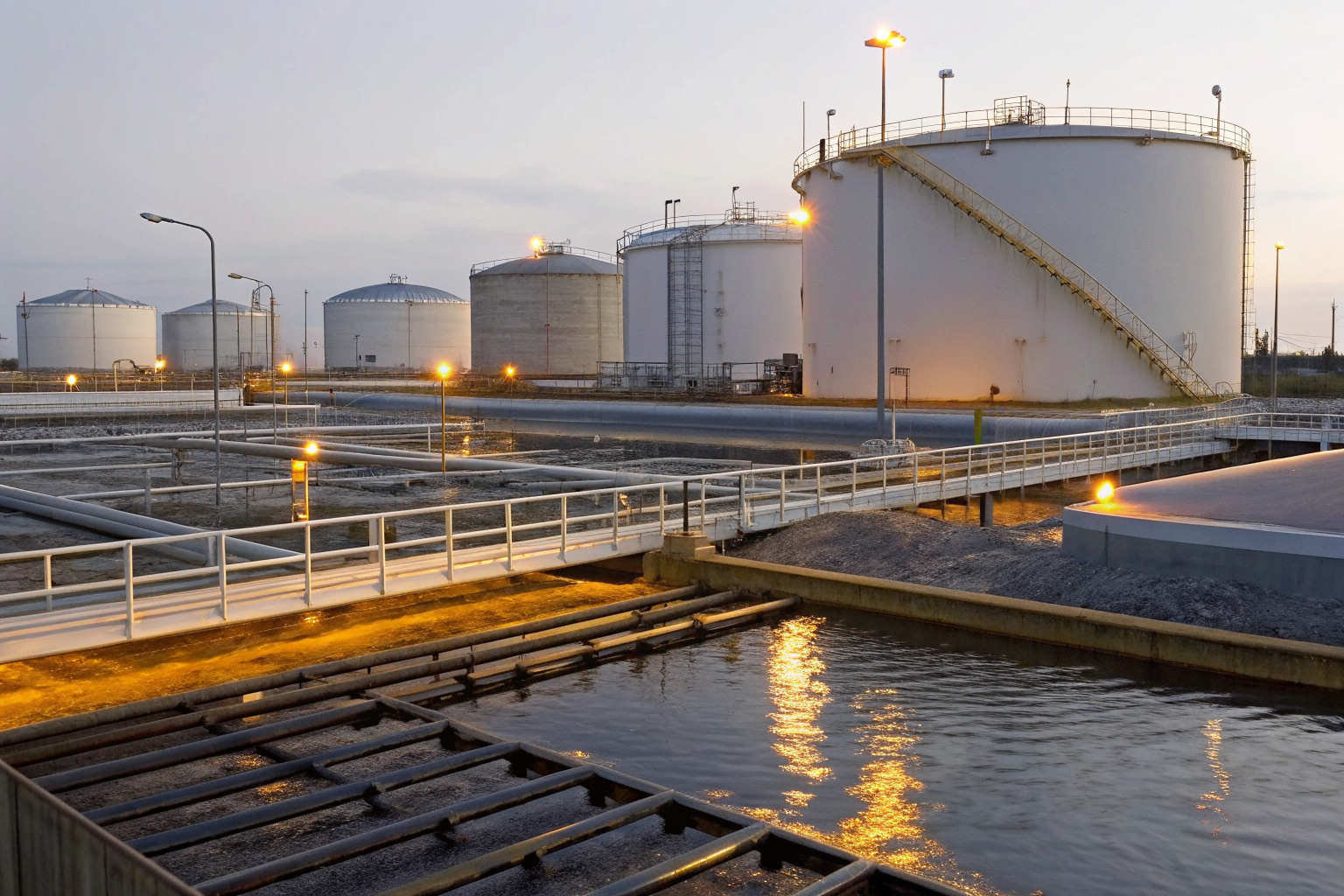
Secondary containment drainage requirements are EPA-mandated specifications that govern how facilities manage water accumulation in containment systems around oil storage tanks. This means every bulk storage facility must design, install, and operate drainage systems that prevent both oil spills and water overflow violations.
EPA Regulations mandate drainage system specifications under 40 CFR 112.8, which requires containment areas to handle the volume of the largest tank plus sufficient freeboard for precipitation. Secondary Containment systems must incorporate drainage mechanisms that allow water removal while maintaining spill prevention integrity.
The connection between drainage requirements and SPCC Plan compliance runs deeper than most facility managers realize. Your SPCC Plan must document specific procedures for water removal, valve operations, and inspection schedules. Drainage Systems become a critical component of your overall spill prevention strategy, not just a water management convenience.
Compliance framework centers on three core principles: containment volume adequacy, controlled drainage operations, and documented water removal procedures. The EPA doesn’t care about your facility’s convenience — they care about preventing oil from reaching navigable waters through any pathway, including overflow from water-logged containment areas.
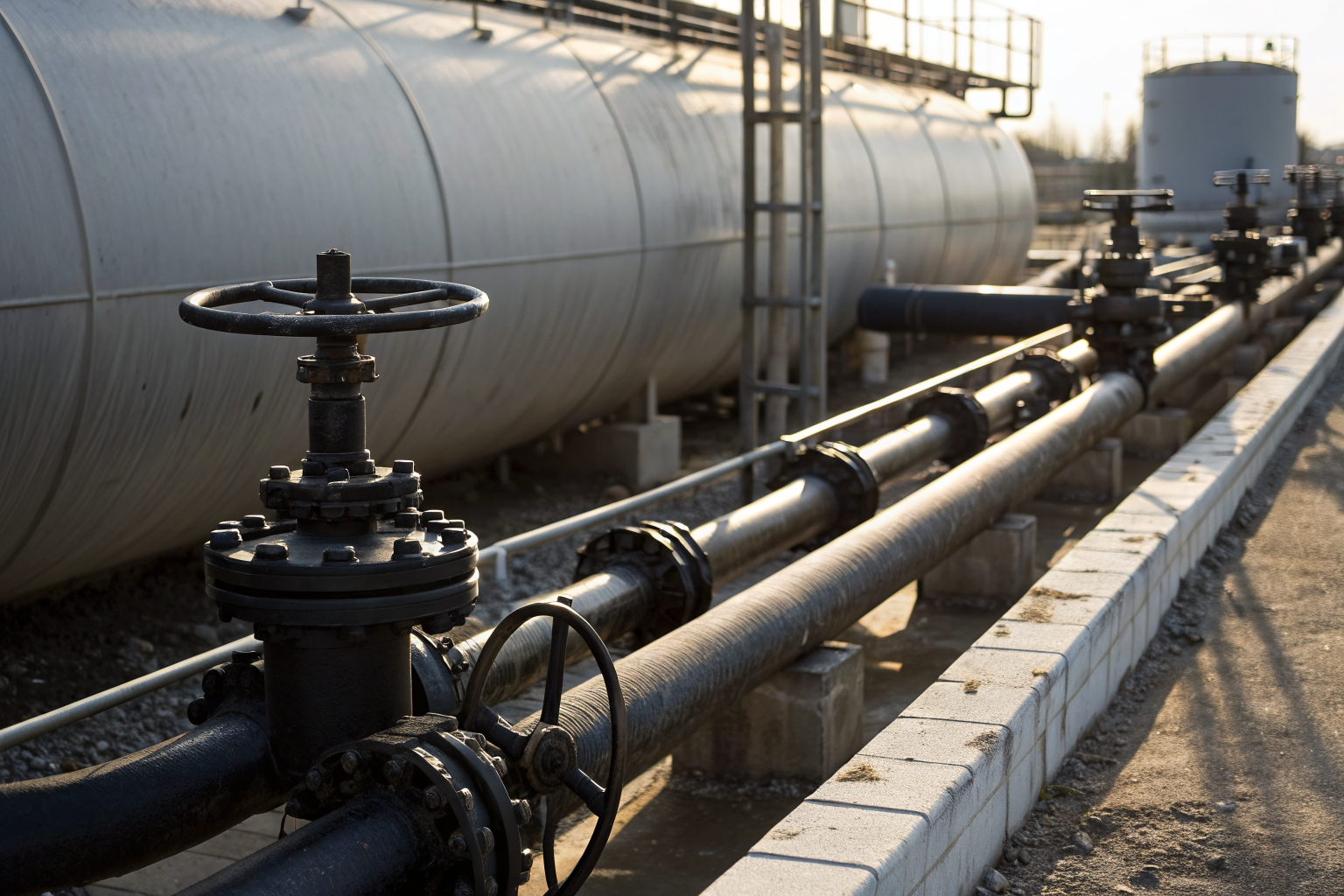
How Do Containment Drain Valves Work?
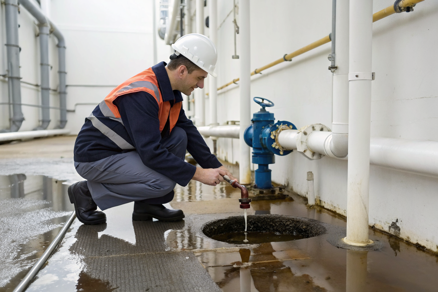
Drain valves control water removal procedures through a specific operational sequence that maintains spill prevention integrity while managing precipitation accumulation.
Step 1: Inspect the containment area for any signs of oil contamination before valve operation. Containment Systems require visual confirmation that no oil sheen or floating product exists in the accumulated water.
Step 2: Document the inspection findings in your facility log. EPA auditors will examine these records during compliance reviews to verify proper procedures.
Step 3: Open the drain valve slowly to control water flow rate. Drainage Systems must allow gradual water removal to prevent hydraulic surges that could damage containment walls or disturb any settled contaminants.
Step 4: Monitor the discharge throughout the drainage process. Stop immediately if oil appears in the discharge water.
Step 5: Close the valve completely once water removal is complete. Valve closure requirements during normal operations are absolute — drain valves must remain closed except during active, supervised water removal.
Step 6: Record the drainage event with date, time, operator name, and volume removed.
Manual valve operation provides superior control compared to automated systems. Automated controls can malfunction during critical moments, potentially releasing contaminated water or failing to operate when containment areas reach capacity. The 67% reduction in containment failure rates with manual inspection protocols stems from human oversight catching problems that sensors miss.
Spill Prevention depends on trained operators who understand that drain valves represent potential release points. Every valve operation carries environmental risk that must be managed through careful procedures and documentation.
Managing Stormwater in Secondary Containment
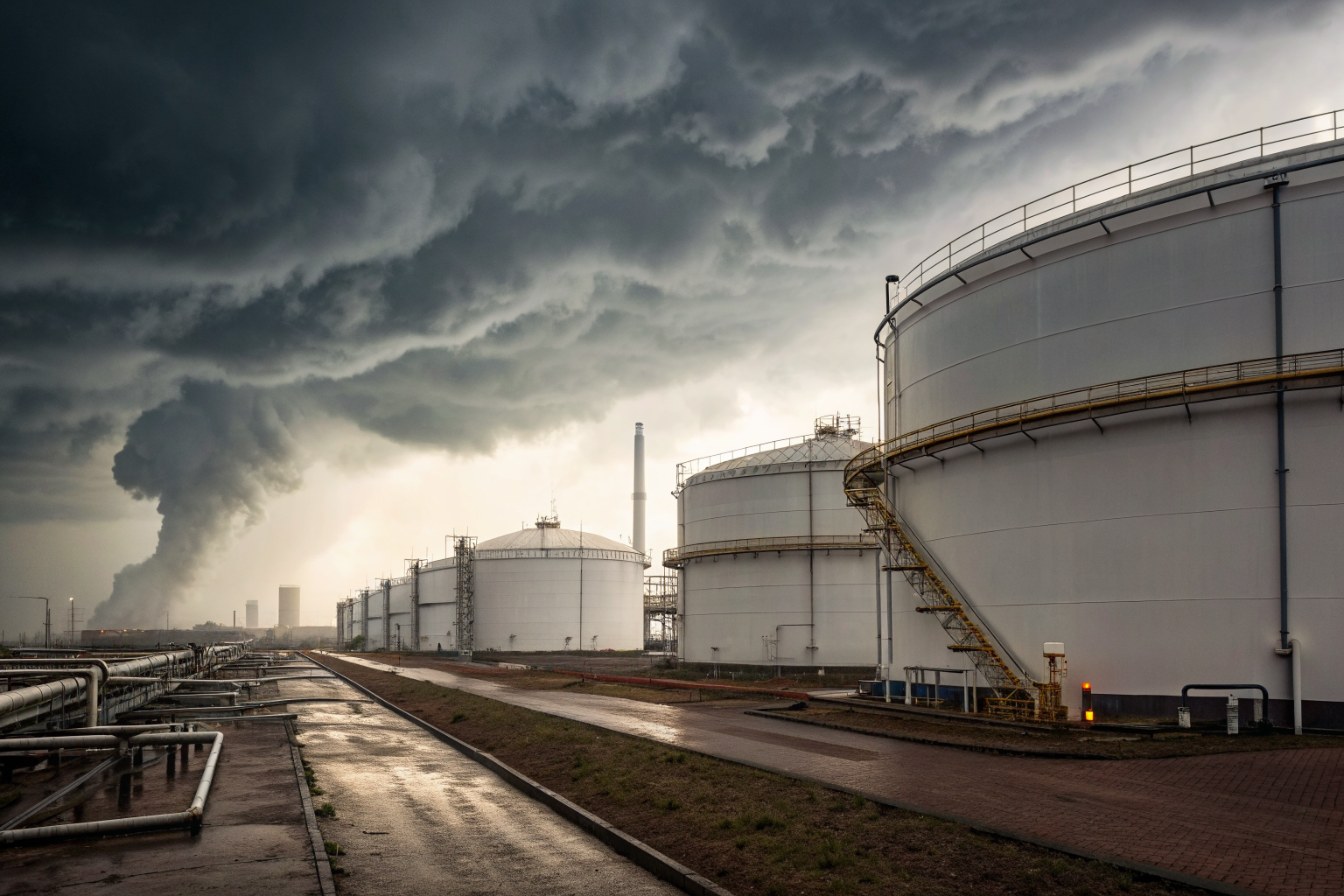
Precipitation accumulates in Secondary Containment areas following predictable patterns that facility managers must understand to maintain compliance and prevent overflow violations.
Rainfall collects in containment areas faster than most operators expect. A 4-inch rainfall event on a 10,000 square foot containment area generates approximately 25,000 gallons of water. Containment Systems designed for oil spill volumes suddenly face massive water loads that can overwhelm capacity within hours.
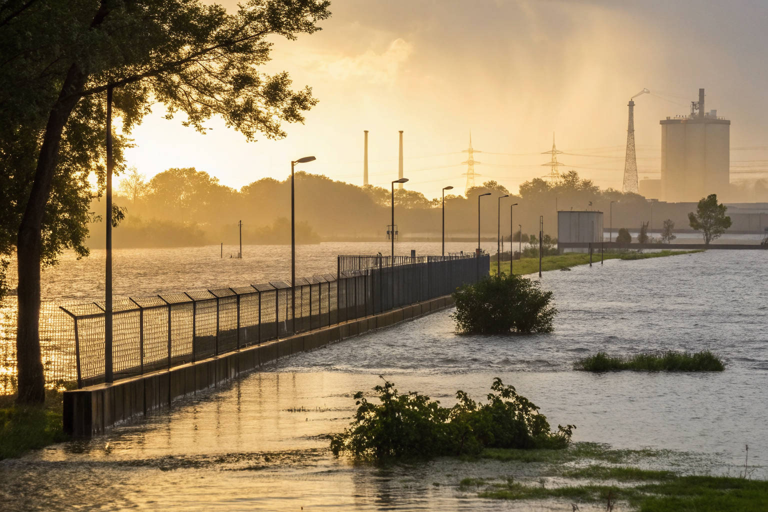
Stormwater management requires proactive removal before accumulation reaches critical levels. The 24-48 hour removal timeframe requirements reflect EPA recognition that precipitation creates ongoing operational challenges. Facilities in high-rainfall regions often struggle with this timing, especially during extended storm periods when continuous precipitation prevents safe drainage operations.
Overflow prevention becomes critical during storm seasons. Water that overtops containment walls carries any oil contamination directly into surrounding soil or surface water. This scenario triggers immediate reporting requirements under SPCC regulations and can result in significant penalties.
Containment area design must account for regional precipitation patterns. Gulf Coast facilities face different challenges than southwestern operations. Your drainage capacity calculations should reflect local weather data, not generic industry standards. Facilities that ignore regional precipitation patterns consistently face overflow violations during storm seasons.
Water removal timing depends on oil contamination status. Clean precipitation can be removed quickly after proper inspection. Water contaminated with oil requires treatment or disposal as hazardous waste, complicating removal procedures and extending containment exposure time.
Temporary storage solutions become necessary when precipitation removal cannot occur within required timeframes. Portable pumping equipment allows emergency water removal when fixed drainage systems cannot handle accumulated volumes.
Drainage System Design Requirements for Oil Storage
Oil Storage requires specific drainage specifications based on tank capacity, containment volume, and facility location characteristics.
| Storage Type | Containment Volume | Drain Valve Size | Material Specification | Installation Standard |
|---|---|---|---|---|
| Single AST <10k gal | 110% tank volume + 1 ft freeboard | 4-inch minimum | Stainless steel or equivalent corrosion resistance | Below frost line, gravity flow preferred |
| Multiple AST <10k gal each | 100% largest tank + 10% others + precipitation | 6-inch minimum | Chemical resistant materials per stored product | Redundant valve system required |
| Bulk Storage >10k gal | 110% largest tank + precipitation allowance | 8-inch minimum | API-approved materials | Automatic shutoff capability |
| Underground tanks | 150% tank volume (where applicable) | 3-inch minimum | Cathodic protection compatible | Double-wall monitoring integration |
| Mobile/portable tanks | 110% tank volume | 2-inch minimum | Portable valve systems acceptable | Temporary installation standards |
Capacity calculations must account for simultaneous oil spill and precipitation events. Bulk Storage facilities cannot assume these events occur separately. Your worst-case scenario involves a tank failure during a major storm event, requiring containment systems to handle both maximum oil volume and significant precipitation simultaneously.
Drainage Systems require sizing based on removal rate capabilities, not just static volume. A large-capacity containment area with inadequate drainage creates compliance problems during extended precipitation periods. Flow rate calculations should allow complete water removal within 24 hours under normal operating conditions.
Material specifications vary by stored product type. Containment areas for gasoline require different drainage materials than diesel storage facilities. Chemical compatibility affects long-term system reliability and maintenance requirements.
Installation standards mandate proper slope design to prevent water pooling in containment areas. Flat-bottom containment areas create dead zones where water accumulates beyond drainage system reach, leading to chronic compliance problems.
Water Removal Procedures and SPCC Compliance

SPCC Plan mandates water removal procedures through specific documentation and inspection requirements that facilities must implement to maintain regulatory compliance.
Step 1: Establish written procedures for precipitation removal that identify responsible personnel, inspection criteria, and decision-making protocols for contaminated water handling.
Step 2: Train operators on proper inspection techniques to distinguish between clean precipitation and oil-contaminated water. Visual inspection standards must be consistent across all facility personnel.
Step 3: Document every drainage event with operator signature, contamination assessment, volume removed, and discharge destination. EPA Regulations require these records for compliance verification.
Step 4: Implement inspection frequency requirements based on facility risk profile and regional precipitation patterns. High-risk facilities require daily inspections during storm seasons.
Step 5: Establish emergency procedures for containment area overflow situations, including immediate notification protocols and temporary storage options.
Step 6: Schedule periodic system testing to verify drainage capacity and valve functionality before storm seasons begin.
Documentation requirements extend beyond simple logbook entries. Water Removal procedures must include photographic evidence of containment area conditions, particularly when oil contamination is suspected. Digital documentation provides timestamp verification that EPA auditors increasingly expect during compliance reviews.
Inspection protocols require specific training on contamination identification. Personnel must distinguish between oil sheen from recent spills and naturally occurring organic films from vegetation or atmospheric deposition. This distinction determines whether accumulated water can be discharged or requires treatment as contaminated waste.
Violation penalties for improper water removal range from $10,000 to $40,000 per incident, depending on environmental impact and facility compliance history. Repeat violations trigger enhanced enforcement actions that can include facility shutdown orders.
Common Drainage System Failures and Prevention
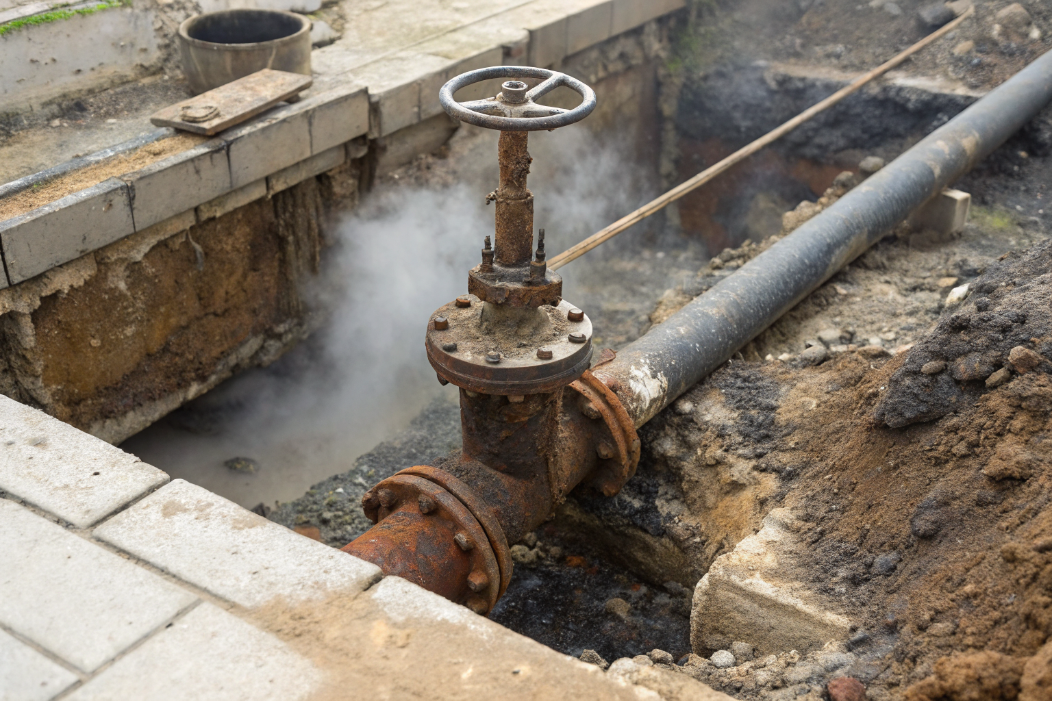
Drainage Systems fail due to maintenance deficiencies that create cascading problems affecting both spill prevention capabilities and regulatory compliance.
Valve failure represents the most common drainage system problem. Drain valves exposed to weather and chemical vapors corrode faster than facility managers expect. Metal components suffer pitting and seal degradation that allows uncontrolled leakage or prevents proper closure. Facilities that defer valve maintenance consistently face emergency repairs during storm events when drainage becomes critical.
Clogged drainage lines create backup problems that reduce system capacity when needed most. Sediment accumulation, debris from containment area cleaning, and biological growth restrict flow rates. Containment Systems depend on unobstructed drainage to prevent overflow violations during precipitation events.
Slope degradation over time creates water pooling in areas beyond drainage system reach. Settlement, frost heave, and heavy equipment traffic alter containment area grades. Water trapped in these dead zones cannot be removed through normal drainage operations, creating chronic compliance problems.
Maintenance schedules prevent most drainage system failures when properly implemented. Quarterly valve inspections, annual drainage line flushing, and periodic slope verification catch problems before they create compliance violations. Spill Prevention effectiveness increases dramatically with proactive maintenance compared to reactive repairs.
Cost analysis shows prevention delivers significant savings compared to violation penalties. Comprehensive drainage system maintenance costs approximately $2,000 annually for typical facilities, while single overflow violations average $25,000 in penalties plus cleanup costs.
Equipment redundancy reduces failure impact during critical periods. Facilities with backup pumping systems and portable drainage equipment maintain compliance during primary system failures. Emergency response capabilities become essential during storm seasons when drainage system reliability determines violation risk.
Training programs focusing on drainage system operation reduce human error failures. Personnel who understand proper procedures and can identify system problems early prevent minor issues from becoming major compliance violations.