SPCC Secondary Containment Requirements: Complete Compliance Guide for 2024
EPA fines for SPCC secondary containment violations averaged $127,000 per facility in 2023, with most penalties stemming from improper capacity calculations and drainage system failures. These SPCC secondary containment requirements determine whether your facility faces crushing penalties or operates within regulatory compliance.
Key Takeaways:
- Secondary containment must hold 110% of the largest tank’s capacity plus precipitation volume for 25-year, 24-hour storm events
- 40 CFR 112.7(c) mandates impervious barriers with leak detection systems for all containers exceeding 55 gallons
- Drainage systems require manual operation with positive shutoff valves — automatic drainage violates EPA regulations
What Are SPCC Secondary Containment Requirements?

SPCC secondary containment requirements are EPA-mandated engineering controls that prevent oil discharges from reaching navigable waters or adjoining shorelines. The SPCC Plan mandates Secondary Containment under 40 CFR 112.7(c) for any oil storage container exceeding 55 gallons in capacity. This means facilities storing oil products must install physical barriers around storage areas to capture spills before they contaminate soil or water.
EPA Regulations define secondary containment as “structures or systems designed and operated to prevent any migration of oil from a container to the sole source aquifer, ground water, or surface water.” The regulation applies when your facility stores more than 1,320 gallons of oil in aggregate capacity above ground, or when you have underground storage exceeding certain thresholds. Oil Storage facilities trigger SPCC requirements regardless of whether they’re commercial operations, industrial plants, or agricultural facilities.
The 55-gallon container threshold creates a clear compliance line. Any single container holding 55 gallons or more requires individual secondary containment unless it’s located within a larger containment system. This includes drums, totes, day tanks, and mobile containers that remain stationary for extended periods. The EPA considers “oil” to include petroleum products, vegetable oils, and synthetic oils — essentially any non-petroleum oil that could harm the environment.
Secondary Containment becomes mandatory, not optional, once you exceed these capacity thresholds. The EPA doesn’t provide flexibility based on oil type, container material, or operational frequency. Either you meet the requirements or you’re in violation. Facilities often discover this during their first SPCC inspection, when they realize their 275-gallon tote requires the same containment standards as a 10,000-gallon tank.
The regulation’s scope extends beyond storage tanks to include piping, loading areas, and transfer operations. Any location where oil could potentially discharge requires containment appropriate to that risk level. This comprehensive approach means SPCC Plans must address every point in your oil handling system where a release could occur.
How Do You Calculate Secondary Containment Capacity?
Containment Systems must hold 110% tank capacity plus additional precipitation volume to meet SPCC requirements. This calculation determines the minimum containment size your facility needs for regulatory compliance.
Step 1: Calculate Base Containment Volume
Multiply your largest tank capacity by 1.10 to get the base containment requirement. A 10,000-gallon tank requires 11,000 gallons of containment capacity minimum. For multiple tanks within the same containment area, use 110% of the largest tank plus 10% of all remaining tanks.
Step 2: Determine Precipitation Volume
Add precipitation volume for a 25-year, 24-hour storm event specific to your geographic region. The National Weather Service provides precipitation data showing storm volumes ranging from 3.5 inches in arid regions to 8+ inches in high-rainfall areas. Multiply this depth by your containment area’s footprint to get the precipitation volume in gallons.
Step 3: Account for Freeboard Requirements
Include additional freeboard space above the calculated volume. EPA guidance recommends 12-24 inches of freeboard to prevent overflow during actual spill events. Bulk Storage facilities in high-precipitation regions often require 18+ inches of freeboard to handle combined spill and storm volumes.
Step 4: Calculate Total Required Capacity
Add base containment volume + precipitation volume + freeboard space. For example, a 10,000-gallon tank in a region with 6-inch, 25-year storm events requires: 11,000 gallons (base) + 1,200 gallons (precipitation for 2,000 sq ft containment) + 600 gallons (freeboard) = 12,800 gallons total containment capacity.
Step 5: Verify Multiple Tank Scenarios
For containment areas with multiple tanks, calculate the worst-case scenario where the largest tank completely empties. The containment must hold this volume plus 10% of all other tanks plus precipitation. This prevents cascade failures where one tank rupture causes others to overflow their containment.
Precipitation calculations vary significantly by region. Southwestern facilities might add 1,000 gallons for storm volume, while Gulf Coast facilities could require 3,000+ gallons for the same containment area. The EPA requires site-specific precipitation data, not generic national averages.
What Structural Standards Must Secondary Containment Meet?
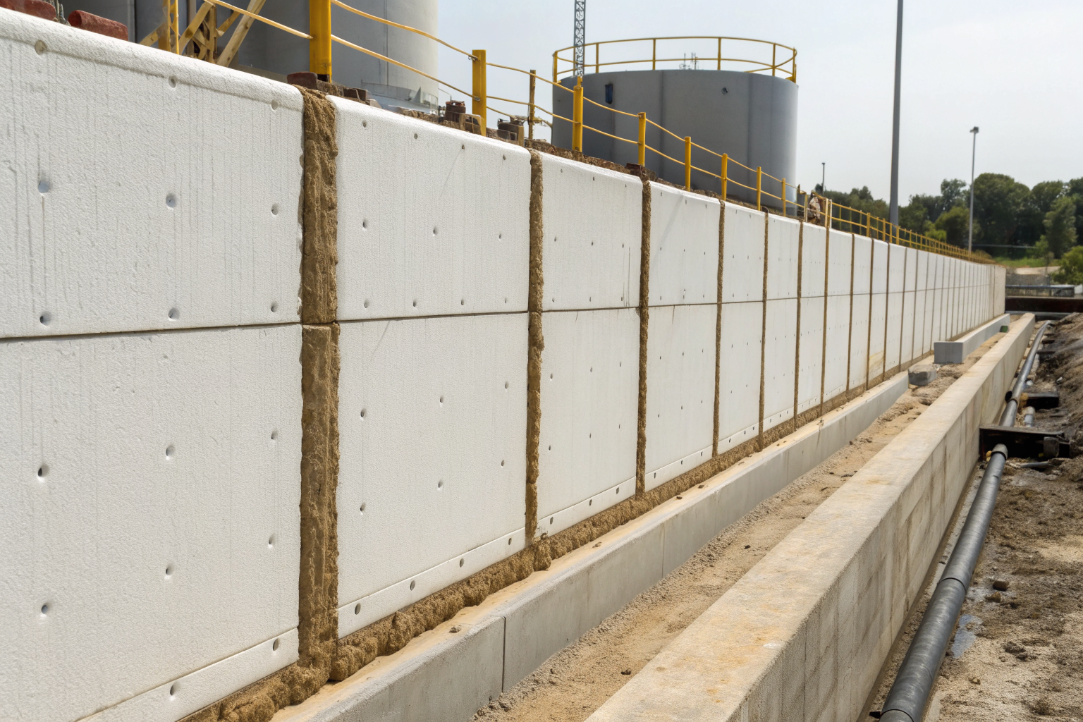
Structural Integrity prevents oil discharge through engineered barriers that meet specific material and construction standards. Containment Systems must demonstrate impermeability, structural stability, and compatibility with stored oil products.
| Component | Specification | Performance Standard | Inspection Requirement |
|---|---|---|---|
| Concrete Walls | Min 6″ thick, 4,000 PSI | Permeability <1×10^-7 cm/sec | Annual crack inspection |
| Steel Liner | 16-gauge minimum | ASTM A36 or equivalent | Monthly visual check |
| Foundation | 4″ reinforced concrete | Vapor barrier required | Annual settlement survey |
| Joints/Seams | Welded or sealed | Leak-proof construction | Quarterly seal inspection |
| Wall Height | 110% capacity + freeboard | 42″ minimum height | Annual capacity verification |
| Drainage Valve | Manual operation only | 6″ above floor minimum | Monthly operation test |
Concrete containment requires permeability rates under 1×10^-7 cm/sec to prevent oil migration through the barrier. This specification eliminates standard concrete mixes, requiring specialized low-permeability concrete with chemical admixtures or protective coatings. Steel thickness requirements mandate 16-gauge minimum for liner systems, with heavier gauges for high-volume or corrosive applications.
Foundation standards demand 4-inch reinforced concrete with vapor barriers to prevent ground contamination. The EPA considers foundation failure a critical violation because subsurface oil migration is nearly impossible to remediate completely. Proper foundation design includes French drains, monitoring wells, and leak detection systems that alert operators to barrier breaches.
Containment Systems must withstand hydrodynamic pressure from stored oil plus hydrostatic pressure from accumulated precipitation. Wall design calculations include live loads, dead loads, and seismic considerations for earthquake-prone regions. The structural engineer’s stamped drawings become part of your SPCC Plan documentation.
Seam specifications require continuous welds or approved sealant systems that maintain integrity under thermal cycling and chemical exposure. Expansion joints must accommodate temperature changes without creating leak paths. Drainage Systems integrate into the containment structure with sloped floors directing spills toward collection points.
How Should Drainage Systems Be Designed for SPCC Compliance?

Drainage Systems require manual operation under EPA regulations to prevent accidental oil discharge during precipitation events. This design philosophy prioritizes spill containment over automatic water removal.
Manual vs. Automatic Drainage Comparison:
| System Type | Regulatory Status | Operator Requirements | Risk Level |
|---|---|---|---|
| Manual Valves | EPA Approved | Daily inspection during storms | Low discharge risk |
| Automatic Timers | Prohibited | None (system operates alone) | High violation risk |
| Float-Activated | Prohibited | None (responds to water level) | Moderate discharge risk |
| Remote Manual | EPA Approved | Trained operator control | Low risk with protocols |
Manual drainage systems use positive shutoff valves positioned 6 inches above the containment floor minimum. This elevation prevents oil discharge even when the valve remains open, since oil floats on water and accumulates at the surface. Valve positioning follows API 620 specifications for materials handling and includes lockout/tagout capabilities for maintenance safety.
Spill Prevention protocols require visual inspection before valve operation. Operators must confirm no oil sheen appears on accumulated water before opening drainage valves. This inspection prevents the most common violation: discharging oily water during precipitation removal. Facilities develop written procedures specifying inspection criteria, valve operation sequences, and documentation requirements.
Precipitation management becomes complex when storm volumes exceed containment capacity. Manual systems allow controlled water release while maintaining oil containment, but require 24/7 operator availability during extended storm events. Remote-operated manual valves provide operational flexibility while maintaining EPA compliance, since human judgment remains in the decision loop.
Valve specifications must resist corrosion from oil exposure and provide leak-tight shutoff under operating pressure. Gate valves work better than ball valves for infrequent operation, while butterfly valves suit high-volume drainage applications. The EPA requires valve maintenance records showing operational testing and seal replacement schedules.
Drainage system design includes oil-water separators for contaminated precipitation that cannot discharge directly. These systems process accumulated water through API separator technology before environmental release, ensuring discharge meets local water quality standards.
What Are Common Secondary Containment Compliance Failures?

EPA Regulations penalize inadequate containment through enforcement actions that target specific technical violations and operational deficiencies. Most facilities fail compliance due to design errors rather than intentional violations.
Capacity miscalculations represent 67% of EPA enforcement actions based on 2023 inspection data. Facilities consistently underestimate precipitation volumes or misapply the 110% rule for multiple tank configurations. The EPA finds facilities using 100% tank capacity instead of 110%, or ignoring precipitation entirely in their containment sizing. These calculation errors result in undersized containment that fails during actual spill events.
Drainage system violations occur when facilities install automatic drainage to reduce maintenance burden. The EPA considers any automatic drainage system a direct path for oil discharge, regardless of oil-water separation equipment or float switch designs. Facilities receive violations even when automatic systems never actually discharge oil, because the potential for discharge violates the regulation.
Structural deficiencies include cracked concrete, failed seams, and inadequate foundation systems that allow oil migration. EPA inspectors use dye testing to identify leak paths through containment barriers. Foundation settlements create the most expensive remediation requirements, since fixing foundation problems often requires complete containment reconstruction.
Secondary Containment inspection failures stem from inadequate maintenance records and missing structural assessments. The EPA requires annual inspections documenting containment integrity, but many facilities treat this as a paperwork exercise rather than genuine engineering evaluation. Missing documentation triggers immediate violations regardless of actual containment condition.
Oil Storage facilities frequently fail to update their SPCC Plans when adding containers or modifying operations. The EPA requires plan amendments within six months of capacity changes exceeding 1,000 gallons. Facilities operating under outdated plans face violations for inadequate containment even when their actual systems meet current requirements. This administrative violation often compounds technical violations during EPA enforcement actions.