Drum Dispensing Station Containment: Safe Solutions for Drum Taps and Pumps
Drum dispensing stations create the highest spill risk per operation in industrial facilities — one loose coupling during transfer operations can dump 55 gallons in under two minutes. Proper drum dispensing station containment prevents these catastrophic releases while meeting EPA regulatory requirements.
Key Takeaways:
- EPA requires 110% containment capacity for dispensing areas under 40 CFR 112.8
- Drum tap leaks account for 73% of small-volume spills in manufacturing facilities
- Modular dispensing platforms reduce cleanup time by 85% compared to floor-level operations
What Is Drum Dispensing Station Containment?

Drum dispensing station containment is specialized secondary containment designed to capture spills during active chemical transfer operations. This means the system must handle dynamic risks like operator movement, equipment vibration, and connection failures that don’t exist during passive storage. Unlike static drum storage where containers sit undisturbed, dispensing operations create constant opportunities for human error and mechanical failure.
Secondary containment serves a fundamentally different purpose during dispensing versus storage. Storage containment handles catastrophic drum failures or slow seepage over time. Dispensing containment must capture immediate releases from loose fittings, overfilled containers, or splash-back during transfer. The containment system needs instant response capability because dispensing spills happen fast.
Drum handling during transfer operations multiplies risk factors exponentially. Operators must manipulate taps, position receiving containers, and monitor flow rates while maintaining spill prevention protocols. Each action point creates potential failure modes that passive storage never encounters. EPA regulations recognize this distinction by requiring higher inspection frequencies and more robust containment specifications for active dispensing areas.
The regulatory framework demands 110% containment capacity for dispensing stations under 40 CFR 112.8. This capacity must account for the largest container being dispensed plus additional volume for operational spillage. The regulation assumes dispensing operations will generate more frequent small spills than storage operations, requiring extra capacity beyond the basic drum volume.
Why Do Drum Taps and Pumps Need Specialized Containment?
Drum taps create higher spill frequency than passive storage systems due to mechanical stress and operator interaction. Manual taps experience constant threading, loosening, and repositioning during operations. Each connection cycle introduces wear on gaskets and threading that eventually leads to leakage. Industry data shows manual taps fail at rates 400% higher than sealed storage systems over equivalent time periods.
Electric pumps present different failure modes but equally elevated risks compared to static drum storage. Pump systems include electrical connections, motor housings, and pressure fittings that create multiple potential leak points. Flow control valves add another mechanical interface that can develop seepage over time. Vibration from pump operation gradually loosens connections that remain tight during storage.
Operator error factors multiply during dispensing operations because personnel must actively manage the transfer process. Product selection mistakes, overfilling receiving containers, and improper valve sequencing all generate immediate spills. Storage operations rarely require operator interaction beyond periodic inspections, eliminating most human error scenarios. EPA regulations acknowledge this pattern by requiring enhanced training protocols for dispensing station operators.
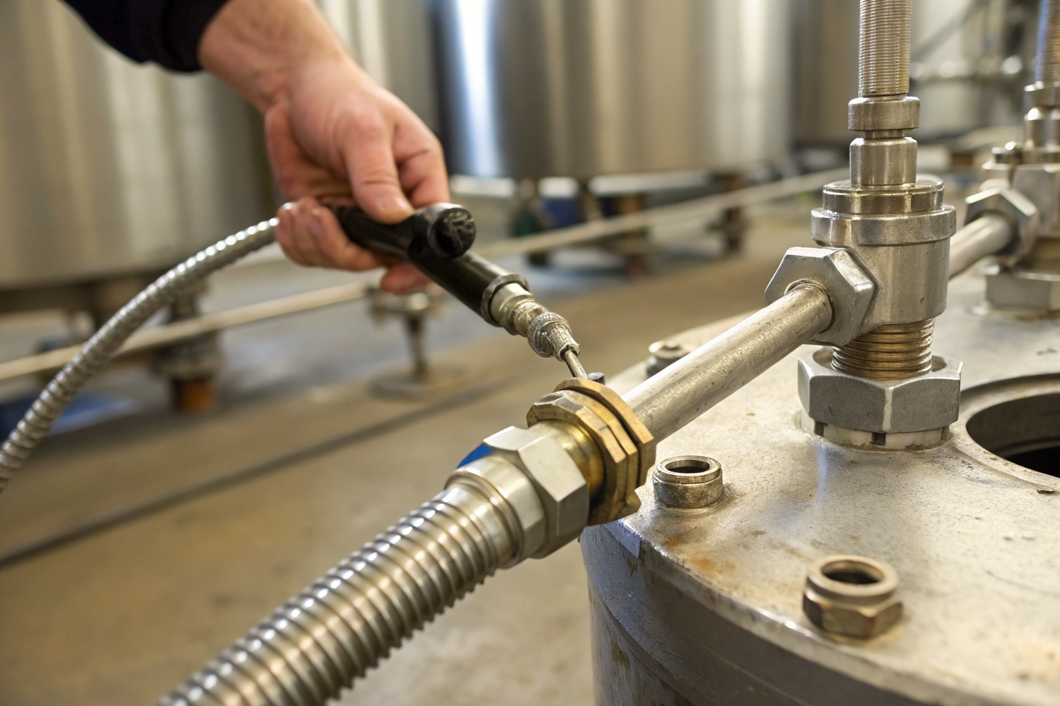
Connection point vulnerabilities represent the highest single failure category in dispensing systems. Threaded connections experience thermal cycling as fluids pass through, causing expansion and contraction that loosens fittings over time. Quick-disconnect couplings accumulate contamination that prevents proper sealing. Flexible hoses develop stress cracks at connection points from repeated movement and pressure cycling.
Drum storage containment handles predictable failure modes like gradual container deterioration or seepage from damaged drums. Dispensing containment must respond to sudden, high-volume releases from active equipment failures. The containment design philosophy shifts from long-term leak collection to immediate spill capture and containment during active operations.
How Do Dispensing Station Spill Pallets Work?

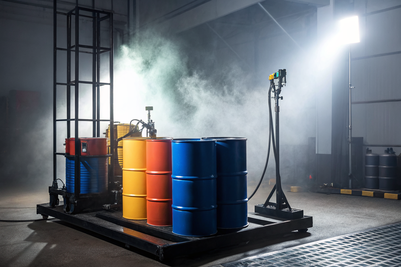
Spill pallets capture dispensing leaks through raised containment walls that create a collection basin around the entire dispensing operation. The containment mechanism starts with an elevated platform that positions drums above the collection area, allowing gravity to direct any spillage into the containment basin rather than onto the facility floor.
Step one involves positioning the drum on the raised platform section of the spill pallet. The platform height typically ranges from 6 to 12 inches above the containment floor, providing clearance for dispensing equipment while maintaining easy access for operators. The raised design prevents spills from escaping the containment area during the critical first seconds after a release.
Step two requires connecting dispensing equipment while maintaining all components within the containment boundaries. Spill pallets feature integrated channels and mounting points for pump electrical cords, preventing trip hazards while keeping all equipment within the containment zone. This ensures electrical components remain protected from chemical exposure during spill events.
Step three implements the drain system management during operations. Most dispensing station pallets include removable drain plugs that remain closed during operations to contain spills, then open for cleaning and maintenance. The drain system connects to appropriate waste collection systems or secondary containment areas as required by facility spill response procedures.
Secondary containment walls on dispensing pallets typically measure 6 inches high and feature reinforced corners to handle the dynamic loads from drum movement and equipment vibration. Standard dispensing pallets provide 66-gallon containment capacity for single 55-gallon drum operations, meeting the EPA’s 110% capacity requirement with additional operational spillage allowance.
Material compatibility becomes critical for dispensing station pallets because the containment surface experiences direct chemical contact during spill events. High-density polyethylene construction resists most industrial chemicals while providing the structural strength needed for repeated drum loading and dispensing operations. Steel pallets with chemical-resistant coatings offer higher load capacity for heavy drum operations.
What Are the Best Pump Containment Solutions?
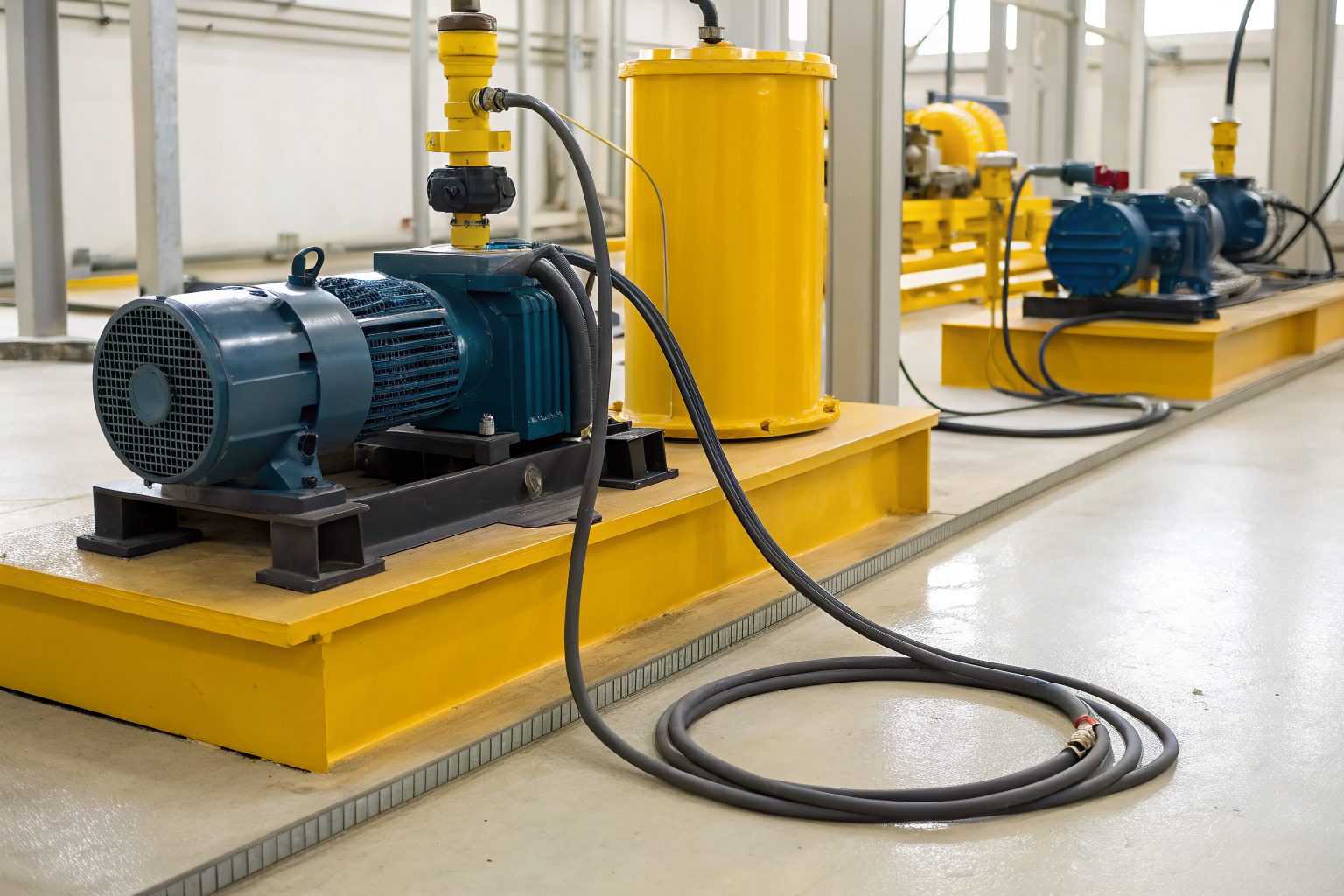
Electric pumps require different containment than manual taps because electrical components add complexity and safety requirements to the containment system. Pump containment must integrate cord management, motor protection, and electrical disconnect accessibility while maintaining spill capture capability. The containment design must prevent chemical contact with electrical components during spill events.
Manual dispensing taps need containment focused on connection point protection and operator workspace organization. Tap containment systems feature tool storage, wrench mounting, and positioning aids that keep all dispensing tools within the containment boundary. This prevents operators from carrying contaminated tools outside the spill control area during operations.
Pump mounting options directly affect containment system design and effectiveness. Drum-mounted pumps require containment systems with integrated pump supports and motor housings. Separate pump stands need containment systems large enough to encompass both drum and pump equipment. Mobile pump carts demand containment systems with access ramps and positioning guides for consistent placement.
Flow control integration varies significantly between pump types and affects containment requirements. Variable speed pumps include electronic controls that require weather protection and spill isolation. Manual flow control systems need containment designs that provide operator access to valves and gauges while maintaining spill boundaries. Remote flow control systems allow operators to work outside the containment area while maintaining process control.
Maintenance access requirements influence pump containment selection because electrical systems need periodic service and inspection. Containment systems must provide adequate clearance for motor removal, electrical connection inspection, and pump rebuilding without compromising spill control capability. Hinged containment sections and removable access panels address maintenance needs while preserving containment integrity.
Pump flow rates determine containment capacity requirements beyond the basic 110% drum volume standard. High-capacity pumps (over 15 GPM) can generate larger operational spills from overfilling or operator error. Containment systems for high-flow pumps typically provide 15-20% additional capacity beyond regulatory minimums to handle operational spillage patterns specific to rapid transfer operations.
How Does This Fit Your SPCC Plan Requirements?

SPCC plans must document dispensing station containment procedures because EPA regulations treat active transfer operations as higher-risk activities requiring enhanced spill prevention measures. The documentation requirements include containment system specifications, inspection schedules, operator training records, and incident response procedures specific to dispensing operations. Your SPCC plan needs detailed procedures for each dispensing station location and chemical type being transferred.
Inspection schedules for dispensing stations differ from storage area requirements because active equipment experiences accelerated wear and higher failure probability. SPCC plans typically require weekly visual inspections of dispensing equipment and monthly integrity testing of containment systems. The inspection protocol must document connection tightness, containment condition, and equipment functionality before each operating period.
Training protocols for dispensing operations require SPCC plan documentation because operator competency directly affects spill prevention effectiveness. The training program must cover proper connection procedures, flow control operation, spill response protocols, and containment system maintenance. Personnel qualifications and retraining schedules become part of the SPCC compliance documentation.
Incident response procedures specific to dispensing spills need separate SPCC plan sections because dispensing releases often involve active equipment that must be safely shut down before cleanup begins. The response protocol includes equipment isolation procedures, electrical safety protocols for pump systems, and containment breach management. Emergency contact procedures must account for the immediate response needs of active spills versus slower storage system releases.
SPCC plan updates become mandatory when adding new dispensing stations or modifying existing containment systems. Any change in containment capacity, equipment type, or operating procedures triggers a plan revision requirement. The updated plan must demonstrate continued compliance with EPA spill prevention standards and include revised inspection and training schedules for the modified operations.