
Secondary Containment Design Standards: Engineering Specifications and Technical Implementation Guide
Secondary containment systems fail not from regulatory gaps, but from fundamental engineering design flaws that could have been prevented with proper technical specifications. These failures cost facilities millions in cleanup costs and regulatory penalties that proper secondary containment design standards could prevent.
Key Takeaways:
• Industry design standards dictate structural integrity requirements beyond basic regulatory minimums
• Load calculations and material specifications determine long-term containment effectiveness
• Engineering tolerances and installation protocols directly impact system performance
Structural Design Standards for Secondary Containment Systems
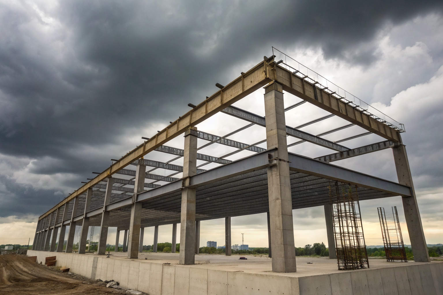
Secondary containment structures must meet structural load requirements that exceed basic regulatory compliance. These engineering specifications determine whether your containment system survives decades of service or fails during the first major storm event.
AISC steel design standards form the backbone of containment wall construction. Steel-framed containment systems require load calculations that account for hydrostatic pressure, wind loads, and seismic forces simultaneously. The structural members must handle these combined stresses without permanent deformation. Secondary containment structures must withstand 150% of maximum anticipated load per AISC guidelines — a safety factor that prevents catastrophic failure during extreme weather events.
ACI concrete specifications govern poured-in-place containment walls and floors. Concrete containment requires specific mix designs that balance structural strength with chemical resistance. The cement type, aggregate gradation, and admixture selection directly impact the system’s ability to contain aggressive chemicals without degradation. Standard concrete mixes fail when exposed to petroleum products or acidic compounds over time.
Live load calculations must include equipment loads, maintenance access loads, and emergency response vehicle loads. Many containment systems fail because designers only calculated the dead load of the structure itself. Live loads from forklifts, maintenance platforms, and emergency pumping equipment can exceed the dead load by 300% during spill response operations. The structural design must accommodate these dynamic loads without compromising containment integrity.
Material specifications must account for chemical compatibility and environmental factors specific to your facility’s operations. Temperature cycling, freeze-thaw conditions, and chemical exposure create material stresses that standard construction materials cannot handle. The specifications must define material properties that maintain structural integrity under these service conditions for the design life of the facility.
Volume Calculations and Capacity Design Requirements
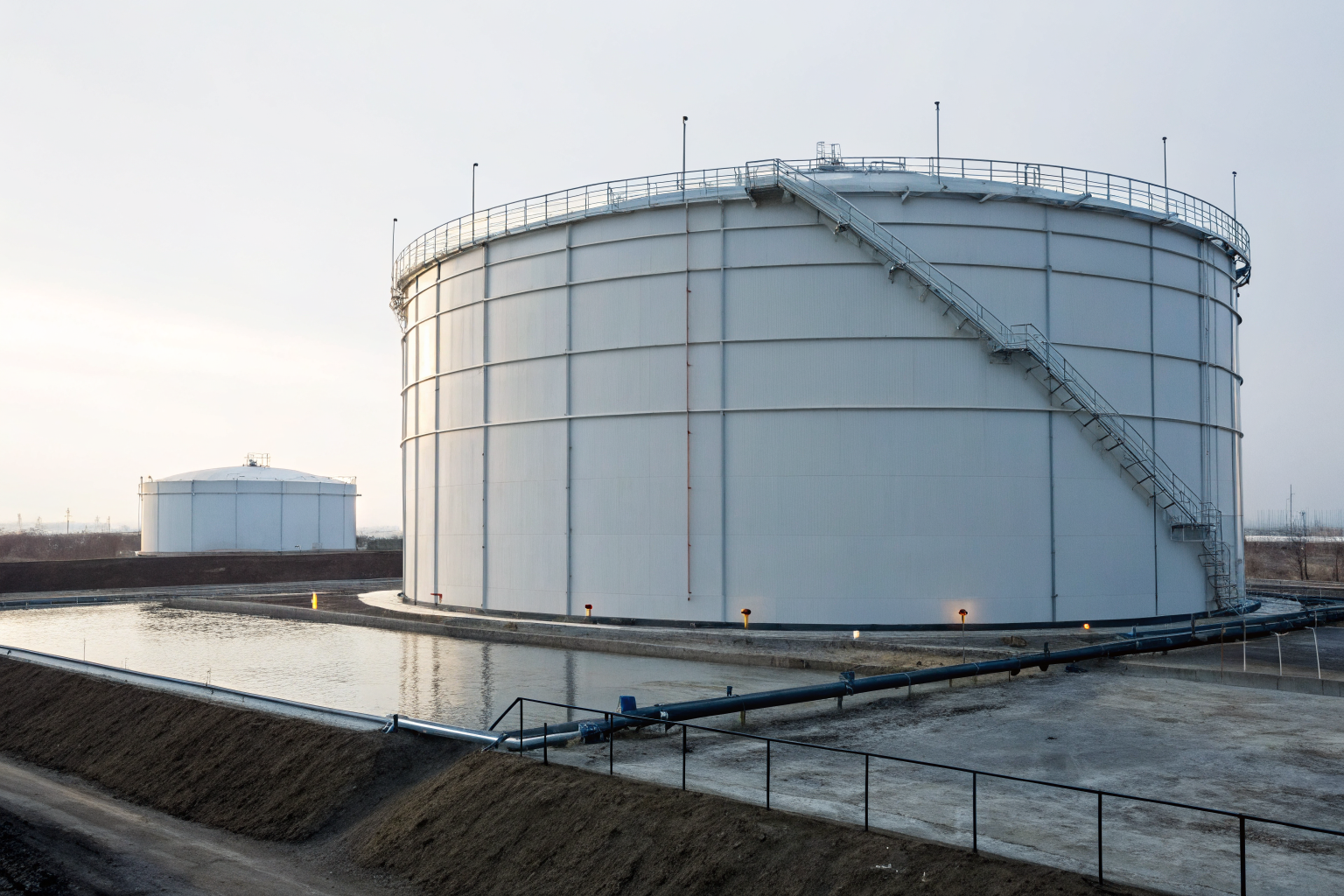
Containment volume equals largest tank capacity plus precipitation allowance through a systematic calculation methodology. This isn’t just the 110% rule — proper volume calculations require integrating multiple load factors that determine actual containment needs during emergency conditions.
Step 1: Calculate the largest single tank volume within the containment area. This becomes your base containment requirement. Include all product stored in the largest tank, not just the nominal capacity.
Step 2: Apply the 110% multiplier to the largest tank capacity. This 10% margin accounts for expansion, measurement uncertainties, and operational variations. Containment volume must equal 110% of largest tank plus 25-year storm precipitation load for most industrial applications.
Step 3: Calculate precipitation load using local meteorological data. The 25-year storm event varies dramatically by geographic region. Desert facilities might add 2 inches while coastal regions require 8+ inches of precipitation capacity. Use National Weather Service historical data for accurate precipitation calculations.
Step 4: Subtract displaced volume from other tanks, piping, and permanent equipment within the containment area. This displaced volume reduces the required containment capacity. However, only subtract volumes that cannot be removed during emergency response operations.
Step 5: Add freeboard requirements mandated by local authorities. Most jurisdictions require 6-12 inches of freeboard above the calculated containment volume. This prevents overflow during dynamic loading conditions like pump-out operations or wind-driven waves in large containment areas.
Regional precipitation data integration requires consulting multiple data sources to ensure accuracy. The NOAA precipitation frequency atlas provides baseline data, but local drainage authorities often have more specific requirements. Industrial facilities near airports or sensitive environmental areas face stricter precipitation calculation requirements that exceed standard engineering practice.
Material Specifications and Chemical Compatibility Standards
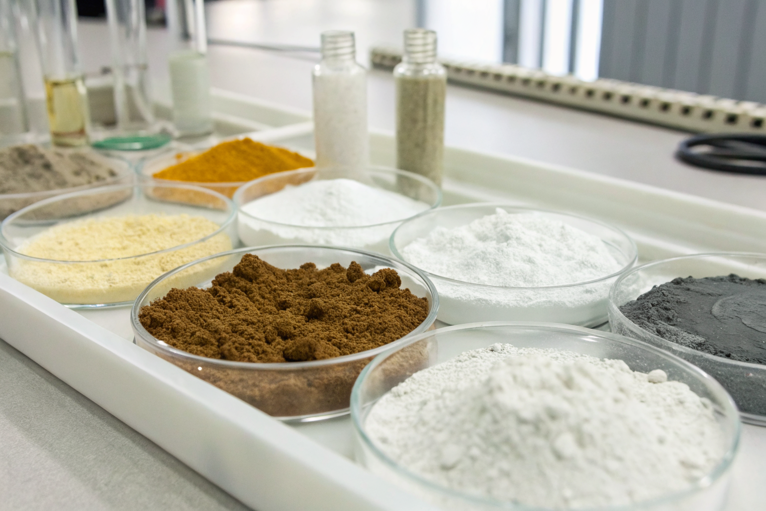
Containment materials must resist specific chemical exposures throughout the design life without performance degradation. Material selection requires analyzing chemical compatibility matrices that match construction materials to stored products and anticipated spill scenarios.
| Material Type | Petroleum Products | Acids (pH 2-4) | Caustics (pH 10-12) | Permeability Rating | Cost Factor |
|---|---|---|---|---|---|
| Standard Concrete | Poor | Excellent | Good | 1×10^-6 cm/sec | 1.0x |
| Polymer Concrete | Excellent | Good | Excellent | 1×10^-8 cm/sec | 2.5x |
| Steel (Coated) | Excellent | Poor | Poor | N/A | 1.8x |
| HDPE Liner | Excellent | Good | Excellent | 1×10^-12 cm/sec | 3.2x |
| FRP Composite | Good | Excellent | Good | 1×10^-9 cm/sec | 4.1x |
ASTM material standards define testing protocols for chemical resistance and permeability. ASTM C267 governs chemical resistance testing for concrete materials. The test exposes material samples to actual stored chemicals for extended periods, measuring strength loss and permeability changes. Many materials that appear chemically compatible fail these long-term exposure tests.
Chemical resistance ratings use standardized scales that rate material performance from A (excellent) to D (not recommended). However, these ratings assume specific concentrations and temperatures. Petroleum products at ambient temperature might rate differently than heated crude oil or winterized diesel fuel. The material specifications must account for actual operating conditions, not laboratory standards.
Permeability coefficients determine how quickly chemicals migrate through containment materials. Concrete containment requires permeability coefficient below 1×10^-7 cm/sec for petroleum products to prevent ground contamination. Standard concrete typically achieves 1×10^-6 cm/sec permeability, requiring admixtures or surface treatments to meet containment standards. Polymer-modified concrete or applied membrane systems achieve the required permeability levels.
Drainage and Pumping System Design Specifications
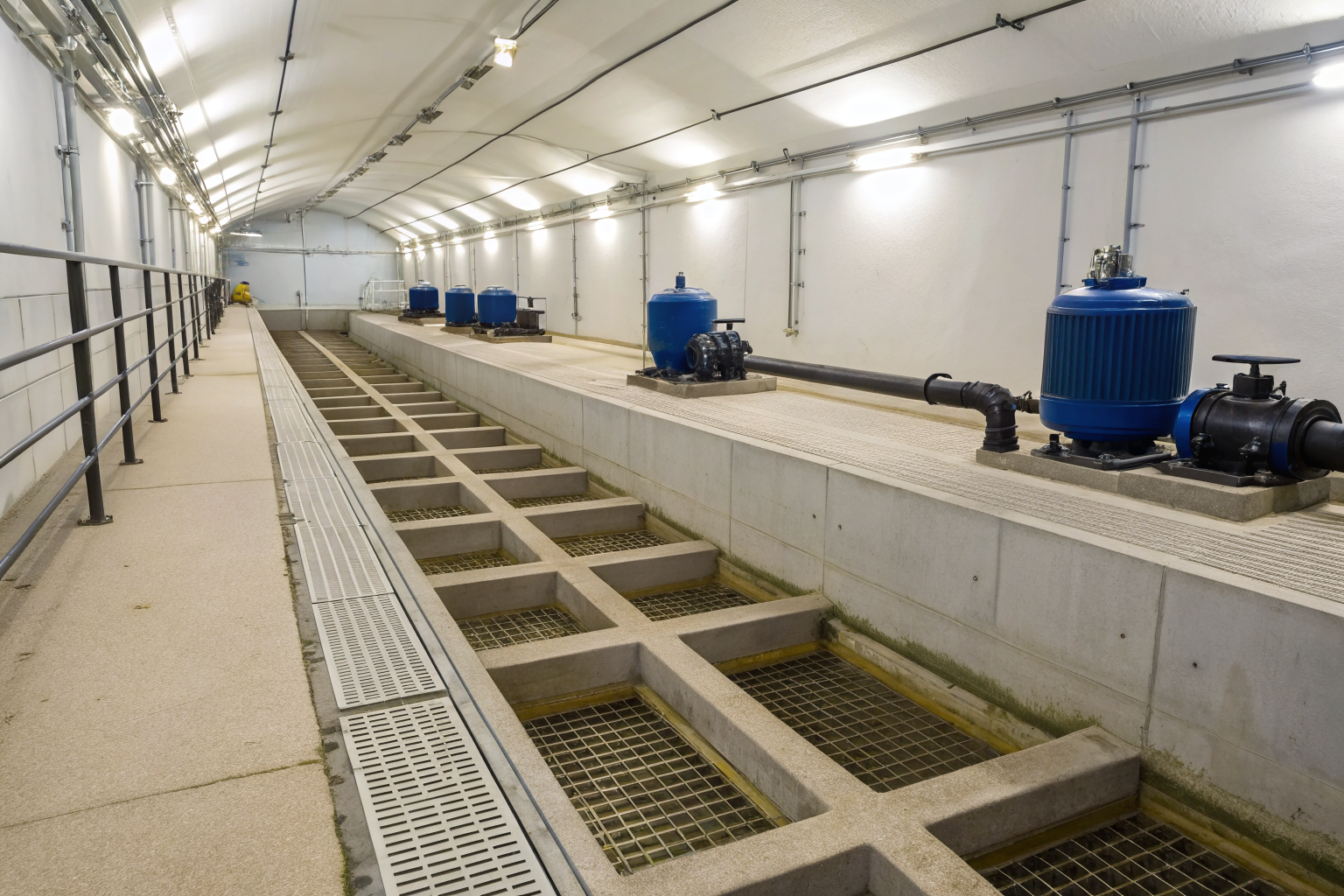
Drainage systems must achieve complete liquid removal through properly sized pumps and sloped surfaces. Inadequate drainage design creates standing water that compromises containment effectiveness and creates maintenance problems.
Step 1: Design containment floors with minimum slope requirements. Containment floors require minimum 1% slope toward drainage points to ensure complete liquid removal. Flat floors create dead spots where spilled liquids accumulate and cannot be removed by pumping systems.
Step 2: Calculate pump capacity based on containment volume and emergency response requirements. The pump must remove the entire containment volume within 24-48 hours depending on regulatory requirements. Size pumps for continuous operation at maximum head pressure, not just initial pumping conditions.
Step 3: Select valve specifications that prevent backflow and provide positive shutoff. Manual valves allow operator control during emergencies, but automatic systems prevent human error. The valve materials must resist the same chemical exposures as the contained products.
Step 4: Design redundant pumping systems for critical applications. Single pump systems create single points of failure that compromise emergency response. Redundant pumps ensure continued operation if the primary pump fails during spill response operations.
Pump sizing calculations must account for head losses through piping, valves, and discharge elevation. Many pumping systems fail because designers only calculated static head, ignoring friction losses through the discharge system. The pump curves must show adequate capacity at actual operating conditions, not just manufacturer ratings at ideal conditions.
Foundation and Geotechnical Design Requirements

Foundation design prevents ground contamination through subsurface migration by creating impermeable barriers beneath containment systems. Geotechnical analysis determines the foundation requirements based on soil conditions and groundwater protection needs.
Soil permeability testing determines natural soil conditions and foundation treatment requirements. Foundation systems require soil permeability below 1×10^-6 cm/sec or engineered liner installation to prevent contaminant migration. Standard soil testing measures permeability at different depths to identify permeable layers that require treatment.
Engineered liner systems provide containment when natural soils exceed permeability limits. HDPE liners, bentonite clay, and compacted clay systems each provide different performance characteristics. HDPE offers superior chemical resistance but requires careful installation to prevent puncture. Bentonite systems self-heal minor punctures but degrade in some chemical environments.
Groundwater monitoring requirements influence foundation design depth and liner specifications. Facilities above shallow groundwater require more stringent foundation treatments than those with deep groundwater. The foundation design must prevent contaminant migration to groundwater regardless of seasonal water table fluctuations.
Subgrade preparation requirements ensure proper liner performance and structural support. Remove organic soils, roots, and debris that could puncture liner systems. Compact subgrade soils to specified density to prevent settlement that creates liner stress points. Grade subgrade surfaces smooth to prevent sharp objects from damaging liner materials during installation.
Foundation drainage systems prevent hydrostatic pressure buildup that could damage containment structures. French drains or leak detection systems beneath liners provide early warning of containment failure. These systems require regular maintenance to prevent clogging that renders them ineffective.
Installation Tolerances and Quality Control Standards

Installation procedures must follow specific tolerance requirements to ensure structural integrity and containment effectiveness. Construction tolerances directly impact system performance and regulatory compliance.
Step 1: Establish wall plumbness tolerances during construction. Wall plumbness must maintain tolerance within 1/4 inch per 10 feet of height to prevent stress concentrations and ensure proper joint sealing. Out-of-plumb walls create gaps in joint systems that compromise containment.
Step 2: Verify concrete placement and consolidation meets ACI standards. Proper consolidation eliminates voids and honeycombing that create leak paths through containment walls. Vibration patterns and duration must follow specified procedures to achieve proper concrete density.
Step 3: Test joint sealing systems during installation. Joint sealants require surface preparation, primer application, and proper curing conditions. Test joint integrity using low-pressure water testing before system commissioning.
Step 4: Document installation procedures and deviations from specifications. Quality control documentation provides evidence of proper construction and identifies areas requiring additional attention during commissioning testing.
Testing protocols during construction phases prevent costly corrections after system completion. Concrete strength testing verifies mix design performance under actual placement conditions. Steel welding requires non-destructive testing to ensure joint integrity meets structural requirements.
Performance Testing and Commissioning Protocols
Containment systems require hydrostatic testing before operation to verify structural integrity and identify potential failure points. Systematic testing procedures ensure the containment system performs as designed under actual service conditions.
Step 1: Fill containment area with clean water to design level. Use potable water to prevent contamination during testing. Monitor filling rate to prevent thermal shock or rapid loading that could damage structural elements.
Step 2: Maintain design water level for minimum 24 hours with less than 1% volume loss. Hydrostatic testing must maintain design water level for minimum 24 hours with less than 1% volume loss to demonstrate containment effectiveness. Measure water level using calibrated gauges at multiple locations.
Step 3: Inspect all joints, connections, and structural elements during the test period. Document any seepage, settlement, or structural movement. Minor seepage through concrete is normal, but active leaks require correction before system acceptance.
Step 4: Test drainage and pumping systems under loaded conditions. Verify pump capacity and drainage effectiveness with the containment area flooded. This testing identifies pump sizing errors and drainage problems before emergency conditions occur.
Step 5: Conduct final inspection and documentation review. Compile all testing data, inspection reports, and construction documentation. Create as-built drawings showing actual construction details and any deviations from original specifications.
Commissioning checklists ensure systematic evaluation of all containment system components. The checklist must cover structural elements, drainage systems, monitoring equipment, and emergency response procedures. Complete commissioning documentation provides baseline performance data for future inspection and maintenance programs.